LinuxCNC S-Curve Accelerations
- andypugh
-

- Away
- Moderator
-

Less
More
- Posts: 19863
- Thank you received: 4636
23 Dec 2021 23:15 #229834
by andypugh
Replied by andypugh on topic LinuxCNC S-Curve Accelerations
The "shopping list" for a LinuxCNC motion planner is quite extensive.
It needs to support 9 axis blending (well, that might be optional, we don't really have that now)
It needs lookahead to cope with small segments but also needs to handle feed-override.
It should ideally support kinematics, staying within axis _and_ joint position, velocity and acceleration limits. (possibly only joints matter)
Please Log in or Create an account to join the conversation.
- Grotius
-

- Offline
- Platinum Member
-

Less
More
- Posts: 2419
- Thank you received: 2348
24 Dec 2021 11:40 #229877
by Grotius
Replied by Grotius on topic LinuxCNC S-Curve Accelerations
Hi Andy,
I have a replacement for the look ahead during runtime. When gcode is loaded an algo calculates the optimal velocity profile.
This is a preprocess offline solution and has no look ahead [x] line limit in forward or at backwards movements.
Inspired by this at line 73 and extended later on.
Feed overide is related to the Velocity max. Quite easy.
I think for a xyz abc path planner we don't have to code any kinematics.
Please Log in or Create an account to join the conversation.
- Aciera
-

- Offline
- Administrator
-

Less
More
- Posts: 4717
- Thank you received: 2113
24 Dec 2021 13:42 #229888
by Aciera
In the current situation any gcode that is to be used on a machine with non-trivial kinematic needs to be run in a simulation first or it may very well risk to run into joint-limits during run time.
Replied by Aciera on topic LinuxCNC S-Curve Accelerations
One 'flaw' of the current planner is that it knows nothing about any custom kinematics used. The custom kinematic calculations are done after the planner has calculated the path (using trivial kinematics). This means that it cannot correctly 'see' any limit violations of a real non-trivial machine. To correctly do that the planner would have to use the custom kinematic and continuously recalculate the machine limits according to the changing joint positions.I think for a xyz abc path planner we don't have to code any kinematics.
In the current situation any gcode that is to be used on a machine with non-trivial kinematic needs to be run in a simulation first or it may very well risk to run into joint-limits during run time.
The following user(s) said Thank You: Grotius
Please Log in or Create an account to join the conversation.
- Grotius
-
- Offline
- Platinum Member
-
Less
More
- Posts: 2419
- Thank you received: 2348
24 Dec 2021 14:48 - 24 Dec 2021 14:49 #229890
by Grotius
Replied by Grotius on topic LinuxCNC S-Curve Accelerations
Hi Arciera,
You can see it as a 'flaw'.
Just like the look ahead replacement algo that calculates the optimal trajectory offline,
The kinematic outputs can be checked by a preprocess function also offline with a fast interval. It does not need to
calculate at the servo cycle accuracy. In a few seconds thousends of gcode line's can be checked offline.
for a 3-6 axis gantry's, there are no kinematics errors. For robots it's another story.
I think checking the kinematics online (in a look ahead function to prevent a too late interupt) it will slurp huge ammounts of memory. On my old pc the servo-load when running a robot with a gcode program is around 50-60% at the moment.
A few preprocess functions will make the software cleaner and faster, and more modular.
If it is done this way, the path planner has no kinematics code inside.
Last edit: 24 Dec 2021 14:49 by Grotius.
Please Log in or Create an account to join the conversation.
- Aciera
-
- Offline
- Administrator
-
Less
More
- Posts: 4717
- Thank you received: 2113
24 Dec 2021 16:02 #229898
by Aciera
Replied by Aciera on topic LinuxCNC S-Curve Accelerations
True, it doesn't have to be planner that does the checking, I'm not even sure it is the planner that checks for limit violations in the current software. All that is required is a limit check using the machines kinematics before it starts moving.
Please Log in or Create an account to join the conversation.
- Grotius
-
- Offline
- Platinum Member
-
Less
More
- Posts: 2419
- Thank you received: 2348
29 Dec 2021 12:23 #230219
by Grotius
Replied by Grotius on topic LinuxCNC S-Curve Accelerations
Hi,
All that is required is a limit check using the machines kinematics before it starts moving.
I don't know if that solves the problem of crashing into machine limits.
If you use a "safe zone" on top of "machine limits" it would problably be unable to crash with full speed into a machine limit.
The "safe zone" is a "distance and maxacc value" where the machine is still able to stop before crashing into machine limit.
For example, when jogging 100% speed x+, the machine will crash into machine limit x at full speed.
When the "safe zone" is active. It will overwrite the jog x+ button to stop perfectly at machine limit x with 0 velocity.
Please Log in or Create an account to join the conversation.
- Grotius
-
- Offline
- Platinum Member
-
Less
More
- Posts: 2419
- Thank you received: 2348
29 Dec 2021 13:24 #230233
by Grotius
Replied by Grotius on topic LinuxCNC S-Curve Accelerations
Hi,
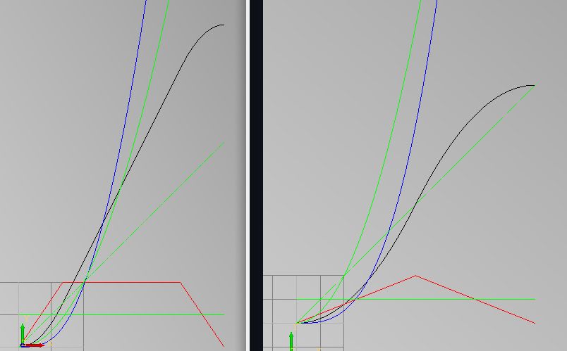
Today i want to show what the benefits of using a scurve with lineair transition period could be.
Picture on the right side:
Scurve with no lineair transition period.
Conventional lineair result:
Picture on the left side:
Scurve with lineair transition period.
Conventional lineair result:
Result:
It looks like the scurve with lineair transition period increases the machine displacement with factor 1.57
The scurve algoritme is suited with a "gain" value instead of "velocity begin and velocity end" value's that are
original used by the sientific papers.
I integrated this modification to simplify the scurve algoritme.
When "gain" value = 0 it outputs a conventional straight acceleration period.
When "gain" value > 0. It outputs a s-curve. (magic happens).
If gain value > 2*velocity it outputs a full scurve without lineair transtion stage. (like ruckig's output).
If gain value < 2*velocity it outputs a curve with lineair transition stage.
So it is a fact, this new algo is more efficient than the ruckig algoritme that has no lineair transition period.
Today i want to show what the benefits of using a scurve with lineair transition period could be.
Picture on the right side:
Scurve with no lineair transition period.
Conventional lineair result:
- time tot:10
- velocity tot:10
- displacment tot:50
- time tot:10
- velocity tot:10
- displacement tot:50
Picture on the left side:
Scurve with lineair transition period.
Conventional lineair result:
- time tot:6.35
- velocity tot:6.35
- displacment tot:20.16
- time tot:6.35
- velocity tot:10
- displacement tot:31.75
Result:
It looks like the scurve with lineair transition period increases the machine displacement with factor 1.57
The scurve algoritme is suited with a "gain" value instead of "velocity begin and velocity end" value's that are
original used by the sientific papers.
I integrated this modification to simplify the scurve algoritme.
When "gain" value = 0 it outputs a conventional straight acceleration period.
When "gain" value > 0. It outputs a s-curve. (magic happens).
If gain value > 2*velocity it outputs a full scurve without lineair transtion stage. (like ruckig's output).
If gain value < 2*velocity it outputs a curve with lineair transition stage.
So it is a fact, this new algo is more efficient than the ruckig algoritme that has no lineair transition period.
Attachments:
The following user(s) said Thank You: robertspark, Darium
Please Log in or Create an account to join the conversation.
- robertspark
- Offline
- Platinum Member
-
Less
More
- Posts: 915
- Thank you received: 216
30 Dec 2021 08:02 #230324
by robertspark
Replied by robertspark on topic LinuxCNC S-Curve Accelerations
is it possible to swap out the motion planner and replace it with this on a working lathe, mill, router or plasma cutter?
if so how would one do it?
( presently using a RIP install)
if so how would one do it?
( presently using a RIP install)
Please Log in or Create an account to join the conversation.
- Darium
- Offline
- New Member
-

Less
More
- Posts: 19
- Thank you received: 0
31 Dec 2021 14:15 #230392
by Darium
Replied by Darium on topic LinuxCNC S-Curve Accelerations
I'm rooting for this project, hope you prevail!!!
Please Log in or Create an account to join the conversation.
- Grotius
-
- Offline
- Platinum Member
-
Less
More
- Posts: 2419
- Thank you received: 2348
01 Jan 2022 20:24 - 01 Jan 2022 20:24 #230477
by Grotius
Replied by Grotius on topic LinuxCNC S-Curve Accelerations
is it possible to swap out the motion planner and replace it with this on a working lathe, mill, router or plasma cutter?
At the moment, no.
if so how would one do it?
In my code solutions it load's as a component. Just as you load a pid or stepgen hal component and then add it to the
servo-thread.
I'm rooting for this project, hope you prevail!!!
It's really a cruel project to code. I am working for weeks on this now. Every day i make little progress.
Some day's i have to start with a new technique to get where i want.
Past day's i have made little progress. The difficulty is now how to deal with user inputs like changing velocity max
during program run. Or when the current gcode line can not reach velocity target etc.
To make things easyer for myself, i decided to give this project a little different approach.
Currently coding a traditional lineair curve setup that deal's with user input senario's.
When this traditional lineair code is finished, i can copy/paste the scurve code into it.
c++ template function for traditional lineair curve. This function can be of type <float> or <double>
video of the function output.
The video shows different senario's like:
1. Gcode input "velocity end [ve]" can not be reached by the given gcode "displacement ", Calculate new [ve].
2. In some cases the "velocity max [vs]" can not be reached. Or the [vs] is changed by user input.
3. Using one or a combined result off: acc period, steady period, dcc period.
Last edit: 01 Jan 2022 20:24 by Grotius.
The following user(s) said Thank You: Darium
Please Log in or Create an account to join the conversation.
Time to create page: 0.244 seconds