LinuxCNC S-Curve Accelerations
- grandixximo
-
 Topic Author
- Away
- Elite Member
-

Less
More
- Posts: 306
- Thank you received: 365
14 Mar 2026 12:08 - 15 Mar 2026 02:05 #344247
by grandixximo
Replied by grandixximo on topic LinuxCNC S-Curve Accelerations
The new PR with comp kinematics support for TP2 will have artifact debs at the end of this link
github.com/LinuxCNC/linuxcnc/actions/runs/23100211514?pr=3807
github.com/LinuxCNC/linuxcnc/actions/runs/23100211514?pr=3807
Last edit: 15 Mar 2026 02:05 by grandixximo.
The following user(s) said Thank You: akb1212, rodw, endian
Please Log in or Create an account to join the conversation.
- automata
- Offline
- Premium Member
-

Less
More
- Posts: 99
- Thank you received: 86
16 Mar 2026 14:32 - 16 Mar 2026 14:58 #344354
by automata
Replied by automata on topic LinuxCNC S-Curve Accelerations
Thanks for the comp file kinematics update.
I am trying that out.In the meantime, I have been experimenting with current update.
I find that the planner type 2 also cannot accelerate across multiple segments. For a file with very small lines, it is not taking up adequate speed and the file execution is very slow. I am going to try to increase the jerk and try it on a real machine too...
The ngc/tap file is also attached.
I was thinking this could be solved with defining zones for acceleration. Where segments with similar kinematic parameters and some tolerance of direction can be accelerated over simultaneously.
I have tried to capture my "Zones" based acceleration idea (using Claude.ai to elaborate on the details).A zone is a group of consecutive path segments that are treated as a single kinematic unit for acceleration planning. Segments are grouped into a zone when they are nearly collinear — i.e., the direction change between them is below a threshold (angle_threshold, default ~0.57°). A zone boundary is created when:
Corner Velocity Constraint: At each zone boundary (a "corner"), the maximum speed the machine can carry through the junction is computed geometricallyradius = path_tolerance / (1 - cos(θ/2))
v_corner = sqrt(a_max × radius)
Zone-Level Bidirectional Velocity Planning: This is where acceleration is actually resolved:
Forward pass — starting from v_start, for each zone compute how fast the machine can exit given the distance and limits:
v_fwd[k 1] = min(max_reachable_from(v_fwd[k]), zone_Vmax, v_corner[k 1])
Backward pass — starting from v_end, do the same in reverse:
v_bwd[k] = min(max_reachable_from(v_bwd[k 1]), zone_Vmax, v_corner[k])
Merge pass — take the minimum at every zone boundary:
v_zone[k] = min(v_fwd[k], v_bwd[k], v_corner[k])
VelocityPlanner.max_reachable_velocity computes how fast you can reach the end of a segment given jerk/accel limits. Zones are then classified as accel, cruise, or decel based on whether the entry/exit velocities rise, stay flat, or fall. Consecutive same-type zones are merged into runs, and one S-curve (7-phase jerk-limited profile from SCurveSolver) is planned per run.This means for a linearized arc with 1000 micro-segments, only ~3–4 S-curve phases are generated (ramp-up, cruise, ramp-down), instead of 1000 independent profiles.
Regards,
-automata
I am trying that out.In the meantime, I have been experimenting with current update.
I find that the planner type 2 also cannot accelerate across multiple segments. For a file with very small lines, it is not taking up adequate speed and the file execution is very slow. I am going to try to increase the jerk and try it on a real machine too...
The ngc/tap file is also attached.
I was thinking this could be solved with defining zones for acceleration. Where segments with similar kinematic parameters and some tolerance of direction can be accelerated over simultaneously.
I have tried to capture my "Zones" based acceleration idea (using Claude.ai to elaborate on the details).A zone is a group of consecutive path segments that are treated as a single kinematic unit for acceleration planning. Segments are grouped into a zone when they are nearly collinear — i.e., the direction change between them is below a threshold (angle_threshold, default ~0.57°). A zone boundary is created when:
- The direction change exceeds the threshold or
- The kinematic limits (v_max, a_max, j_max) differ between adjacent segments
Corner Velocity Constraint: At each zone boundary (a "corner"), the maximum speed the machine can carry through the junction is computed geometricallyradius = path_tolerance / (1 - cos(θ/2))
v_corner = sqrt(a_max × radius)
- path_tolerance = max allowable deviation from the sharp corner (e.g. 0.01 mm)
- θ = junction angle between the two direction vectors
- A 90° corner at 0.01 mm tolerance and a_max=500 gives v_corner ≈ 4.1 mm/s — forces a near-stop
- A collinear junction (θ→0) gives v_corner → ∞ — no speed reduction needed
Zone-Level Bidirectional Velocity Planning: This is where acceleration is actually resolved:
Forward pass — starting from v_start, for each zone compute how fast the machine can exit given the distance and limits:
v_fwd[k 1] = min(max_reachable_from(v_fwd[k]), zone_Vmax, v_corner[k 1])
Backward pass — starting from v_end, do the same in reverse:
v_bwd[k] = min(max_reachable_from(v_bwd[k 1]), zone_Vmax, v_corner[k])
Merge pass — take the minimum at every zone boundary:
v_zone[k] = min(v_fwd[k], v_bwd[k], v_corner[k])
VelocityPlanner.max_reachable_velocity computes how fast you can reach the end of a segment given jerk/accel limits. Zones are then classified as accel, cruise, or decel based on whether the entry/exit velocities rise, stay flat, or fall. Consecutive same-type zones are merged into runs, and one S-curve (7-phase jerk-limited profile from SCurveSolver) is planned per run.This means for a linearized arc with 1000 micro-segments, only ~3–4 S-curve phases are generated (ramp-up, cruise, ramp-down), instead of 1000 independent profiles.
Regards,
-automata
Attachments:
Last edit: 16 Mar 2026 14:58 by automata. Reason: replacing the poor formating
The following user(s) said Thank You: akb1212, MX_Master
Please Log in or Create an account to join the conversation.
- grandixximo
-
Topic Author
- Away
- Elite Member
-
Less
More
- Posts: 306
- Thank you received: 365
16 Mar 2026 22:10 #344373
by grandixximo
Replied by grandixximo on topic LinuxCNC S-Curve Accelerations
There already is some basic merging, I'm sure it can be improved upon
Please Log in or Create an account to join the conversation.
- grandixximo
-
Topic Author
- Away
- Elite Member
-
Less
More
- Posts: 306
- Thank you received: 365
18 Mar 2026 02:10 #344445
by grandixximo
Replied by grandixximo on topic LinuxCNC S-Curve Accelerations
@automata
Did you run it with bigger jerk limits? Can you share your sim configs?
Did you run it with bigger jerk limits? Can you share your sim configs?
Please Log in or Create an account to join the conversation.
- endian
-

- Offline
- Platinum Member
-

Less
More
- Posts: 336
- Thank you received: 132
18 Mar 2026 04:19 #344448
by endian
Replied by endian on topic LinuxCNC S-Curve Accelerations
thanks a lot and 9d branch is now avaible for rip testing with TP2 without spindle sync movement?The new PR with comp kinematics support for TP2 will have artifact debs at the end of this link
github.com/LinuxCNC/linuxcnc/actions/runs/23100211514?pr=3807
Please Log in or Create an account to join the conversation.
- grandixximo
-
Topic Author
- Away
- Elite Member
-
Less
More
- Posts: 306
- Thank you received: 365
18 Mar 2026 05:26 #344449
by grandixximo
Replied by grandixximo on topic LinuxCNC S-Curve Accelerations
Yes, test in sim for now, I have not run on a machine yet, but sim doesn't look too bad
The following user(s) said Thank You: endian, NWE
Please Log in or Create an account to join the conversation.
- endian
-
- Offline
- Platinum Member
-
Less
More
- Posts: 336
- Thank you received: 132
19 Mar 2026 20:04 - 19 Mar 2026 20:15 #344535
by endian
Replied by endian on topic LinuxCNC S-Curve Accelerations
Ive allready tested the last update ...
TP2 and it is working only with simple shapes really well, I did not notice infinity spikes of anything..
no more difficult shaping avaible.. it just froze at cloud of points as G2\G3 transfered to cloud of points .. time spiking increased from last testing
testing only in simulation level ... no real hardware avaible for now
thanks Luca for your job!
Last edit: 19 Mar 2026 20:15 by endian.
Please Log in or Create an account to join the conversation.
- grandixximo
-
Topic Author
- Away
- Elite Member
-
Less
More
- Posts: 306
- Thank you received: 365
20 Mar 2026 04:34 #344541
by grandixximo
Replied by grandixximo on topic LinuxCNC S-Curve Accelerations
You are welcome, still lots to be done, can you share your configuration, does it always freeze on the point cloud? I'd like to replicate. Time spiking meaning the servo thread? Can you share that as well?
The following user(s) said Thank You: endian
Please Log in or Create an account to join the conversation.
- endian
-
- Offline
- Platinum Member
-
Less
More
- Posts: 336
- Thank you received: 132
24 Mar 2026 17:07 - 24 Mar 2026 17:07 #344678
by endian
Replied by endian on topic LinuxCNC S-Curve Accelerations
Hello,
notice > well tuned RT machine with less then 2us latency
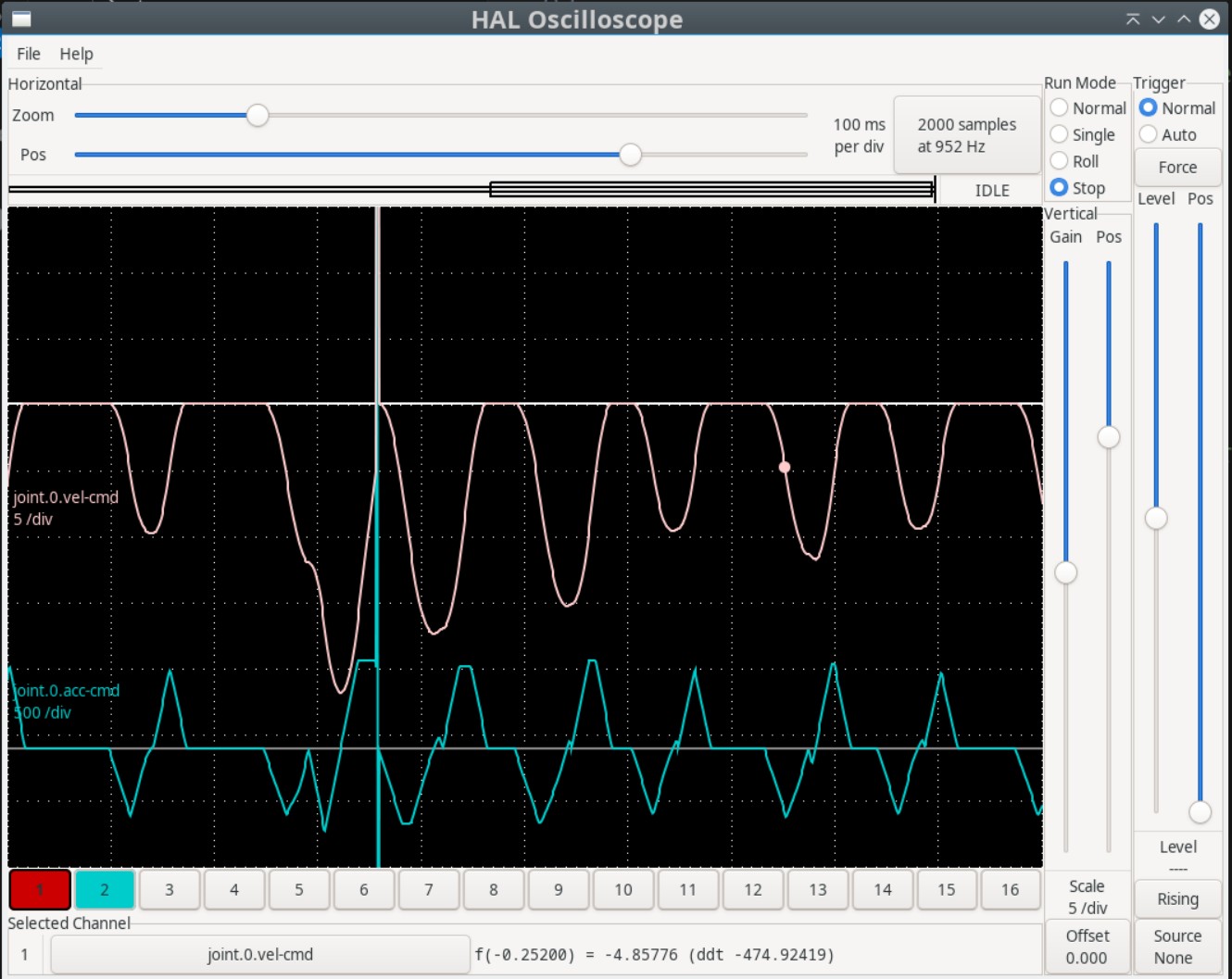
I every time start with the LinuxCNC logo startup file ... create the scope of acc + velocity preview and analyze step by step movement ... jerk 10k m\s3 then I move to the 3d chips and 3d test ... if this works well i am shifting to the my code 1d movement, 2.5 d movement and finally 3d movement .. I start with 0 type then I move to other one for right comparation.. it is freezing TP2 with 3dchips.ngc from default local folder after last update ... no diagnoze possible from my side right now
all step by step analyzing the scopes
Configuration starting basically from axis_mm.ini with custom tool table which is missing from default
Spiking was mainly during start of the scope at servothread and then periodicaly, looks like at each end of segment - but no exact proofing
I am staying tune for more testing or cooperation ...
thanks E.
notice > well tuned RT machine with less then 2us latency
I every time start with the LinuxCNC logo startup file ... create the scope of acc + velocity preview and analyze step by step movement ... jerk 10k m\s3 then I move to the 3d chips and 3d test ... if this works well i am shifting to the my code 1d movement, 2.5 d movement and finally 3d movement .. I start with 0 type then I move to other one for right comparation.. it is freezing TP2 with 3dchips.ngc from default local folder after last update ... no diagnoze possible from my side right now
all step by step analyzing the scopes
Configuration starting basically from axis_mm.ini with custom tool table which is missing from default
Spiking was mainly during start of the scope at servothread and then periodicaly, looks like at each end of segment - but no exact proofing
I am staying tune for more testing or cooperation ...
thanks E.
Last edit: 24 Mar 2026 17:07 by endian. Reason: latency notice add
The following user(s) said Thank You: grandixximo
Please Log in or Create an account to join the conversation.
- grandixximo
-
Topic Author
- Away
- Elite Member
-
Less
More
- Posts: 306
- Thank you received: 365
25 Mar 2026 02:36 #344694
by grandixximo
Replied by grandixximo on topic LinuxCNC S-Curve Accelerations
I will try to replicate, thank you!
The following user(s) said Thank You: endian
Please Log in or Create an account to join the conversation.
Time to create page: 0.567 seconds