- LinuxCNC
- General LinuxCNC Questions
- FPGA (field programmable gate array) programmed for linuxcnc motion
FPGA (field programmable gate array) programmed for linuxcnc motion
- rodw
-

- Offline
- Platinum Member
-

Less
More
- Posts: 12038
- Thank you received: 4108
10 Jul 2018 23:52 #113982
by rodw
Replied by rodw on topic FPGA (field programmable gate array) programmed for linuxcnc motion
Sorry. I had a sore neck!
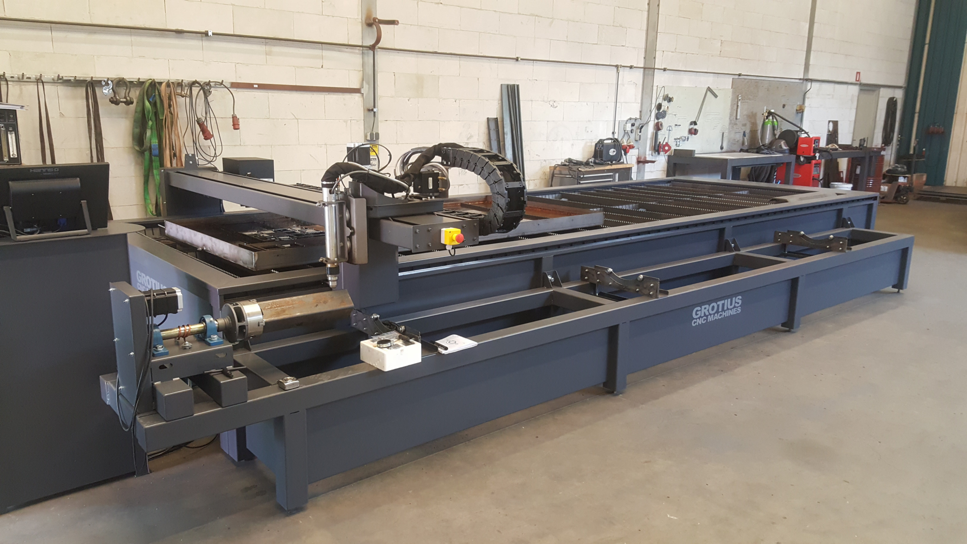
You do make a very nice machine")
You do make a very nice machine
Please Log in or Create an account to join the conversation.
- Grotius
-
 Topic Author
- Offline
- Platinum Member
-
Less
More
- Posts: 2419
- Thank you received: 2348
11 Jul 2018 19:25 - 11 Jul 2018 19:44 #114022
by Grotius
Replied by Grotius on topic FPGA (field programmable gate array) programmed for linuxcnc motion
Hi,
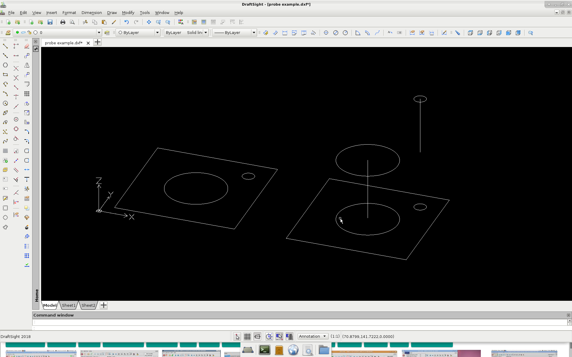
One of my problems with linuxcnc is the probe function, see picture.
Normally without probe, the gremlin screen looks like the left picture.
When i add a linuxcnc G-code based probe function in the post processor, i get a gremlin screen like the right picture.
Problem is : The probe measuring distance you see in the gremlin screen, this is not what i like. How to solve this?
The picture is an example of the problem. The height measuring distance for the probe function is for example 100mm in z axis.
So for a cutting a plate, your screen looks like...
The code looks like this, but i must check that : G91 G38.2 Z-100
Can i make a own gcode or macro in linuxcnc? Where can i find G38.2 in the linux source code?
That would make things easer for me.
Thanks, Rodw. The machine is also working very good with hd plasma. Microstep is far more expensiver. But i must make
a bevel head soon !! This is advice from Hypertherm. So then i must look for a linuxcnc type that can do this. It's a gantry profile + AB axis. I don't know if that exist's at the moment. But first solve a few tiny problem's.
Its a little bit offtopic now, but glad i am no moderator here to put it in the right section.
Last edit: 11 Jul 2018 19:44 by Grotius.
Please Log in or Create an account to join the conversation.
- rodw
-
- Offline
- Platinum Member
-
Less
More
- Posts: 12038
- Thank you received: 4108
11 Jul 2018 21:37 #114032
by rodw
Replied by rodw on topic FPGA (field programmable gate array) programmed for linuxcnc motion
Grotius, I have the same problem with the gremlin preview and mentioned it here forum.linuxcnc.org/plasma-laser/34879-ex...erent-heights#114030
I'm sure there is a solution, I just can't remember it. I think its to use a different coordinate system (G10 L2).
As far as the additional axes go, with the development branch (v2.8), All you need to do is add the extra joints, configure them in hal and change this ini section to something like
I think you also need to add them to the geometry statement so the DRO's display on screen
I hope I got that right. The bevel head would be pretty cool and they don't seem too hard to make.
I'm sure there is a solution, I just can't remember it. I think its to use a different coordinate system (G10 L2).
As far as the additional axes go, with the development branch (v2.8), All you need to do is add the extra joints, configure them in hal and change this ini section to something like
[KINS]
JOINTS     = 6
KINEMATICS = trivkins coordinates=XYYZAB
I think you also need to add them to the geometry statement so the DRO's display on screen
[DISPLAY]
GEOMETRY = XYZAB
I hope I got that right. The bevel head would be pretty cool and they don't seem too hard to make.
Please Log in or Create an account to join the conversation.
- Grotius
-
Topic Author
- Offline
- Platinum Member
-
Less
More
- Posts: 2419
- Thank you received: 2348
12 Jul 2018 18:31 - 12 Jul 2018 18:50 #114081
by Grotius
Replied by Grotius on topic FPGA (field programmable gate array) programmed for linuxcnc motion
Hi Rodw,
Thanks for your excellent tip, this can save lot's of investegation time....
Tomorrow i try this code example on the system, i hope i can solve it soon :
G10 L2 P1 X0 Y0 Z0 (clear offsets for X,Y & Z axes in coordinate system 1)
G10 L2 Set Coordinate System
Program P0 to P9 to specify which coordinate system to change.
This problem i have never seen before, also not seen in any linux cnc online document's.
I wil try to make a test on wiki.linuxcnc.org
hmmm wiki.linuxcnc.org/cgi-bin/wiki.pl?action=editprefs
admin password should be pinguin or tux, but that is not working.
Last edit: 12 Jul 2018 18:50 by Grotius.
Please Log in or Create an account to join the conversation.
- Grotius
-
Topic Author
- Offline
- Platinum Member
-
Less
More
- Posts: 2419
- Thank you received: 2348
13 Jul 2018 20:15 - 13 Jul 2018 20:31 #114146
by Grotius
Replied by Grotius on topic FPGA (field programmable gate array) programmed for linuxcnc motion
Hi Rodw,
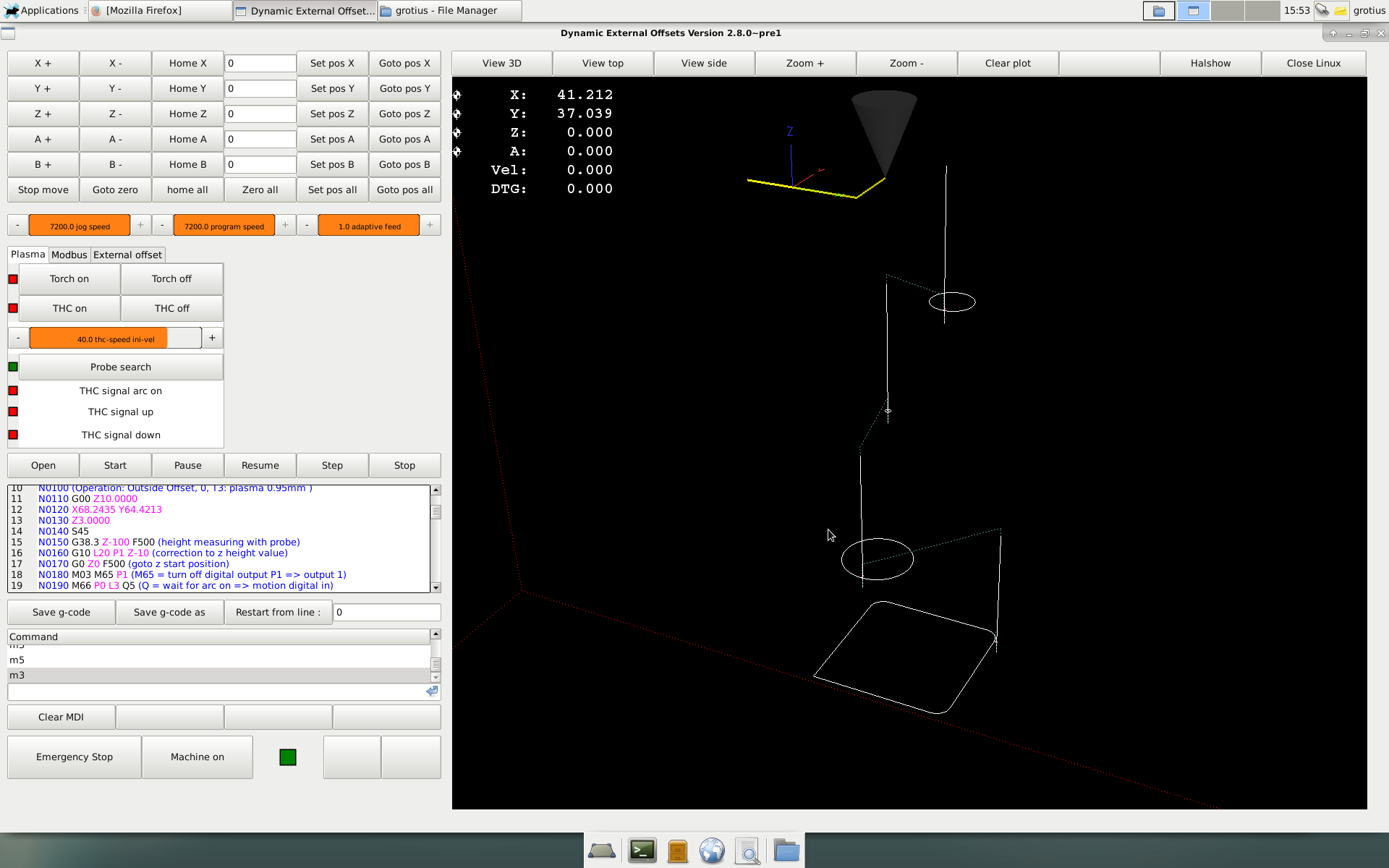
Solution was to change L20 to L2.....
Pff.... very simple....
The bad way :
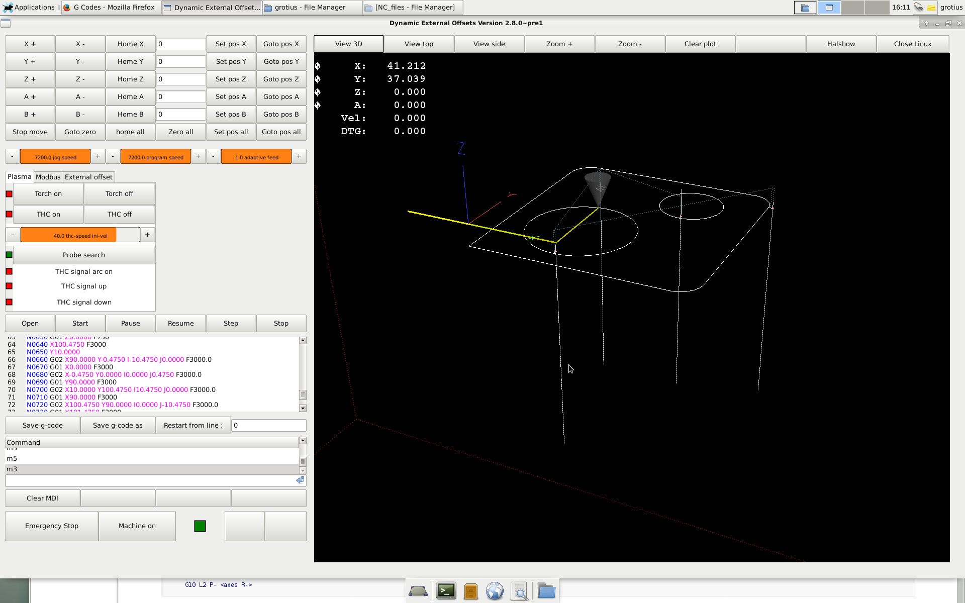
The good way :
For interest, i add the program code. This is done by sheetcam modified postprocessor.
It looks very difficult related to mach3 code.
This is the sheetcam postprocessor i used, just for information. There are a few modifications i did to get things
better working.
This code solution must be tested on a real plasma machine soon. So it is at this moment this solution is not tested !!!
Next problem is to solve the arc on signal during cutting.
The machine waits at start for arc on ....
M66 P0 L3 Q5 (Q = wait for arc on => motion digital in)
This works perfect.
But machine must stop if arc is lost during cutting....
I must find a solution for that....I would like a interrupt poll for this.
Solution was to change L20 to L2.....
Pff.... very simple....
The bad way :
The good way :
For interest, i add the program code. This is done by sheetcam modified postprocessor.
It looks very difficult related to mach3 code.
N0010 (Filename: 1e test ultracut.ngc)
N0020 (Post processor: LinuxCNC plasma - laser.scpost)
N0030 (Date: 05/28/2018)
N0040 G21 (Units: Metric)
N0050 G40 G90
N0060 F1 S1
N0070 G40 G64 P0.005 (machine follow path accuracy)
N0080 M52 P1 (turn on adaptive feed)
N0090 (Part: 1e test ultracut)
N0100 (Operation: Outside Offset, 0, T3: plasma 0.95mm )
N0110 G00 Z10.0000
N0120 X68.2435 Y64.4213
N0130 Z3.0000
N0140 S45
N0150 G38.3 Z-100 F500 (height measuring with probe)
N0160 G10 L2 P1 Z-10 (correction to z height value)
N0170 G0 Z0 F500 (goto z start position)
N0180 M03 M65 P1 (M65 = turn off digital output P1 => output 1)
N0190 M66 P0 L3 Q5 (Q = wait for arc on => motion digital in)
N0200 G04 P0.5
N0210 G01 Z0.0000 F750
N0220 Y62.4213 F3000
N0230 G03 X68.2435 Y62.4213 I0.0000 J14.5250 F3000.0
N0240 G01 Y63.4213 F3000
N0250 M05 M64 P1 (M64 = turn on digital output 1 => remove offsets)
N0260 G00 Z10.0000
N0270 X21.6174 Y77.7952
N0280 Z3.0000
N0290 G38.3 Z-100 F500 (height measuring with probe)
N0300 G10 L2 P1 Z-10 (correction to z height value)
N0310 G0 Z0 F500 (goto z start position)
N0320 M03 M65 P1 (M65 = turn off digital output P1 => output 1)
N0330 M66 P0 L3 Q5 (Q = wait for arc on => motion digital in)
N0340 G04 P0.5
N0350 G01 Z0.0000 F750
N0360 Y75.7952 F3000
N0370 G03 X21.6174 Y75.7952 I0.0000 J2.0250 F3000.0
N0380 G01 Y76.7952 F3000
N0390 M05 M64 P1 (M64 = turn on digital output 1 => remove offsets)
N0400 G00 Z10.0000
N0410 X34.6832 Y10.5482
N0420 Z3.0000
N0430 G38.3 Z-100 F500 (height measuring with probe)
N0440 G10 L2 P1 Z-10 (correction to z height value)
N0450 G0 Z0 F500 (goto z start position)
N0460 M03 M65 P1 (M65 = turn off digital output P1 => output 1)
N0470 M66 P0 L3 Q5 (Q = wait for arc on => motion digital in)
N0480 G04 P0.5
N0490 G01 Z0.0000 F750
N0500 Y8.5482 F3000
N0510 G03 X34.6832 Y8.5482 I0.0000 J24.5250 F3000.0
N0520 G01 Y9.5482 F3000
N0530 M05 M64 P1 (M64 = turn on digital output 1 => remove offsets)
N0540 G00 Z10.0000
N0550 X102.4750 Y90.0000
N0560 Z3.0000
N0570 G38.3 Z-100 F500 (height measuring with probe)
N0580 G10 L2 P1 Z-10 (correction to z height value)
N0590 G0 Z0 F500 (goto z start position)
N0600 M03 M65 P1 (M65 = turn off digital output P1 => output 1)
N0610 M66 P0 L3 Q5 (Q = wait for arc on => motion digital in)
N0620 G04 P0.5
N0630 G01 Z0.0000 F750
N0640 X100.4750 F3000
N0650 Y10.0000
N0660 G02 X90.0000 Y-0.4750 I-10.4750 J0.0000 F3000.0
N0670 G01 X0.0000 F3000
N0680 G02 X-0.4750 Y0.0000 I0.0000 J0.4750 F3000.0
N0690 G01 Y90.0000 F3000
N0700 G02 X10.0000 Y100.4750 I10.4750 J0.0000 F3000.0
N0710 G01 X90.0000 F3000
N0720 G02 X100.4750 Y90.0000 I0.0000 J-10.4750 F3000.0
N0730 G01 X101.4750 F3000
N0740 M05 M64 P1 (M64 = turn on digital output 1 => remove offsets)
N0750 G00 Z10.0000
N0760 M52 P0 (stop adaptive)
N0770 M05 M30 (program end)
This is the sheetcam postprocessor i used, just for information. There are a few modifications i did to get things
better working.
function OnAbout(event)
   ctrl = event:GetTextCtrl()
   ctrl:AppendText("Grotius CNC Machines : plasma and laser post processor\n")
   ctrl:AppendText("\n")
   ctrl:AppendText("Modal G-codes and coordinates\n")
   ctrl:AppendText("Comments enclosed with ( and )\n")
   ctrl:AppendText("Incremental IJ\n")
   ctrl:AppendText("Laser outputs power as spindle speed\n")


end


--  made 23-5-2018


function OnInit()
   post.SetCommentChars ("()", "[]")  --make sure ( and ) characters do not appear in system text
   post.Text (" (Filename: ", fileName, ")\n")
   post.Text (" (Post processor: ", postName, ")\n")
   post.Text (" (Date: ", date, ")\n")
   if(scale == metric) then
      post.Text (" G21 (Units: Metric)\n") --metric mode
   else
      post.Text (" G20 (Units: Inches)\n") --inch mode
   end
   post.Text (" G40 G90\n F1 S1\n")
   post.Text (" G40 G64 P0.005 (machine follow path accuracy) \n")
   post.Text (" M52 P1 (turn on adaptive feed)\n")
   bigArcs = 1 --stitch arc segments together
   minArcSize = 0.05 --arcs smaller than this are converted to moves
end

function OnNewLine()
   post.Text ("N")
   post.Number (lineNumber, "0000")
   lineNumber = lineNumber + 10
end


function OnFinish()
   post.Text (" M52 P0 (stop adaptive)\n")
   post.Text (" M05 M30 (program end)\n")
end

function OnRapid()
   post.ModalText (" G00")
   post.ModalNumber (" X", endX * scale, "0.0000")
   post.ModalNumber (" Y", endY * scale, "0.0000")
   post.ModalNumber (" Z", (endZ + toolOffset) * scale, "0.0000")
   post.Eol()
end

function OnMove()
   post.ModalText (" G01")
   post.ModalNumber (" X", endX * scale, "0.0000")
   post.ModalNumber (" Y", endY * scale, "0.0000")
   post.ModalNumber (" Z", (endZ + toolOffset) * scale, "0.0000")
   post.ModalNumber (" F", feedRate * scale, "0.###")
   if(toolType == 8 or toolType == 9) then
      post.ModalNumber (" S", power, "0.###")
   end
   post.Eol()
end

function OnArc()
   if(arcAngle <0) then
      post.ModalText (" G03")
   else
      post.ModalText (" G02")
   end
   post.NonModalNumber (" X", endX * scale, "0.0000")
   post.NonModalNumber (" Y", endY * scale, "0.0000")
   post.ModalNumber (" Z", (endZ + toolOffset) * scale, "0.0000")
   post.Text (" I")
   post.Number ((arcCentreX - currentX) * scale, "0.0000")
   post.Text (" J")
   post.Number ((arcCentreY - currentY) * scale, "0.0000")
   post.ModalNumber (" F", feedRate * scale, "0.0###")
   post.Eol()
end


function OnPenDown()
   if (preheat > 0.001) then
      post.ModalText (" G00")
      post.ModalNumber (" Z", cutHeight * scale, "0.0000")
      post.Text ("\n G04 P")
      post.Number (preheat,"0.###")
      post.Eol()
   end
   post.ModalText (" G00")
   post.ModalNumber (" Z", pierceHeight * scale, "0.0000")
   post.ModalNumber (" S", power, "0.###")
   post.Text ("\n G38.3 Z-100 F500 (height measuring with probe)\n")
   post.Text ("\n G10 L20 P1 Z-10 (correction to z height value)\n")
   post.Text ("\n G0 Z0 F500 (goto z start position)\n")
   post.Text ("\n M03 M65 P1 (M65 = turn off digital output P1 => output 1)\n")
   post.Text ("\n M66 P0 L3 Q5 (Q = wait for arc on => motion digital in)\n")


   if (pierceDelay > 0.001) then
      post.Text (" G04 P")
      post.Number (pierceDelay,"0.###")
      post.Eol()
   end
end


function OnPenUp()
   post.Text (" M05 M64 P1 (M64 = turn on digital output 1 => remove offsets)\n")
   if (endDelay > 0) then
      post.Text (" G04 P")
      post.Number (endDelay,"0.###")
      post.Eol()
   end
end

function OnNewOperation()
   post.Text (" (Operation: ", operationName, ")\n")
end

function OnComment()
  post.Text(" (",commentText,")\n")
end


function OnNewPart()
   post.Text(" (Part: ",partName,")\n");
end


function OnDrill()
   OnRapid()
   OnPenDown()
   endZ = drillZ
   OnMove()
   OnPenUp()
   endZ = safeZ
   OnRapid()
end
This code solution must be tested on a real plasma machine soon. So it is at this moment this solution is not tested !!!
Next problem is to solve the arc on signal during cutting.
The machine waits at start for arc on ....
M66 P0 L3 Q5 (Q = wait for arc on => motion digital in)
This works perfect.
But machine must stop if arc is lost during cutting....
I must find a solution for that....I would like a interrupt poll for this.
Last edit: 13 Jul 2018 20:31 by Grotius.
Please Log in or Create an account to join the conversation.
- rodw
-
- Offline
- Platinum Member
-
Less
More
- Posts: 12038
- Thank you received: 4108
13 Jul 2018 21:16 - 13 Jul 2018 21:17 #114152
by rodw
Replied by rodw on topic FPGA (field programmable gate array) programmed for linuxcnc motion
Thanks for this. More to understand! I have not selected a coordinate system at all.
Perhaps it is possible to set halui.program-pause when ArcOK is lost when halui.program-is-running. this might need a component to deal with some logic conditions. It would be nice to be able to lift the torch so you can change consumables though.
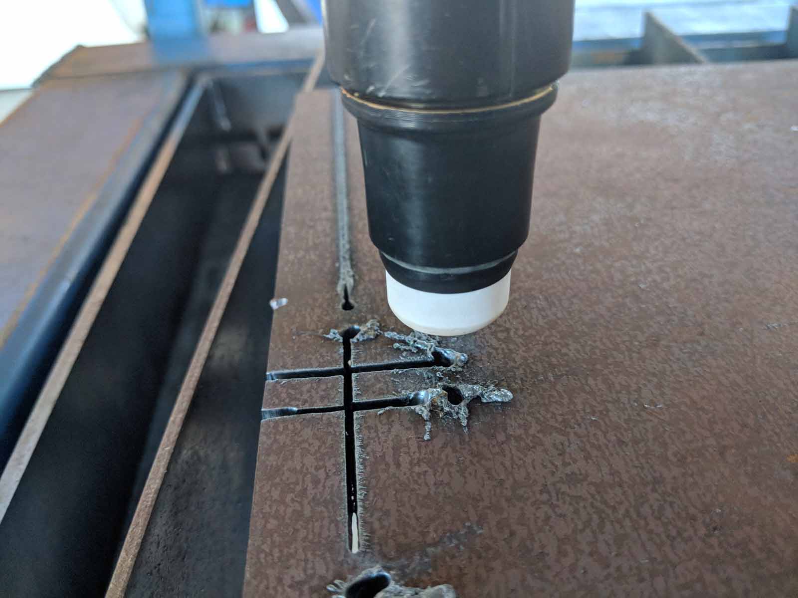
Yesterday I spent some time looking at kerf crossings.
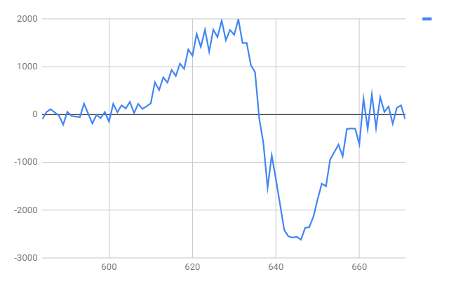
And a plot of the rate of change of voltage at the kerf cross (volts per second)
Still much more to do as this was at 200 ms per reading from halscope
I tried a 1ms capture from halscope but it had no meaningful data so I will repeat using halsampler which I know will sample the data.
Perhaps it is possible to set halui.program-pause when ArcOK is lost when halui.program-is-running. this might need a component to deal with some logic conditions. It would be nice to be able to lift the torch so you can change consumables though.
Yesterday I spent some time looking at kerf crossings.
And a plot of the rate of change of voltage at the kerf cross (volts per second)
Still much more to do as this was at 200 ms per reading from halscope
I tried a 1ms capture from halscope but it had no meaningful data so I will repeat using halsampler which I know will sample the data.
Last edit: 13 Jul 2018 21:17 by rodw.
Please Log in or Create an account to join the conversation.
- Grotius
-
Topic Author
- Offline
- Platinum Member
-
Less
More
- Posts: 2419
- Thank you received: 2348
14 Jul 2018 08:44 - 14 Jul 2018 08:59 #114164
by Grotius
Replied by Grotius on topic FPGA (field programmable gate array) programmed for linuxcnc motion
Hi Rodw,
Do you have problem's with kerf krossing during cutting? I usually tune the thc speed down that it can do kerf crossing
without problem's. In mach3 it is enough to use a thc speed of 35%.
For the solution that stops the movement of machine when plasma arc is lost, i have maybe an idea.
Common used signals :
thcud.arc-ok ( the arc-on signal from torch height control module)
motion.digital−in−00 ( waits only for thcud.arc-ok at plasma start )
halui.spindle.is−on ( tells you the actual status of m3/m5 )
Status g-code signal:
halui.spindle.is−on
inputs :
thcud.enable
thcud.arc-ok
Maybe use this signals combined with a user defined macro and some simple hal logic.
A short g-code example within the external offset branche :
M03 M65 P1 (M65 = turn off digital output P1 => enable offsets)
M66 P0 L3 Q5 (Q = wait for arc on => motion digital in, in this case it waits = Q.. 5 seconds)
M100 P1(enable arc lost signal)
G01 ..... Cutting program
M100 P0 (disable arc lost signal)
M05 M64 P1 (M64 = turn on digital output 1 => remove offsets)
Okey i think this user defined macro is important, otherwise the machine don't know when to look at the arc lost signal.
Last edit: 14 Jul 2018 08:59 by Grotius.
Please Log in or Create an account to join the conversation.
- Grotius
-
Topic Author
- Offline
- Platinum Member
-
Less
More
- Posts: 2419
- Thank you received: 2348
14 Jul 2018 16:55 - 14 Jul 2018 18:17 #114171
by Grotius
Replied by Grotius on topic FPGA (field programmable gate array) programmed for linuxcnc motion
Hi Rodw,
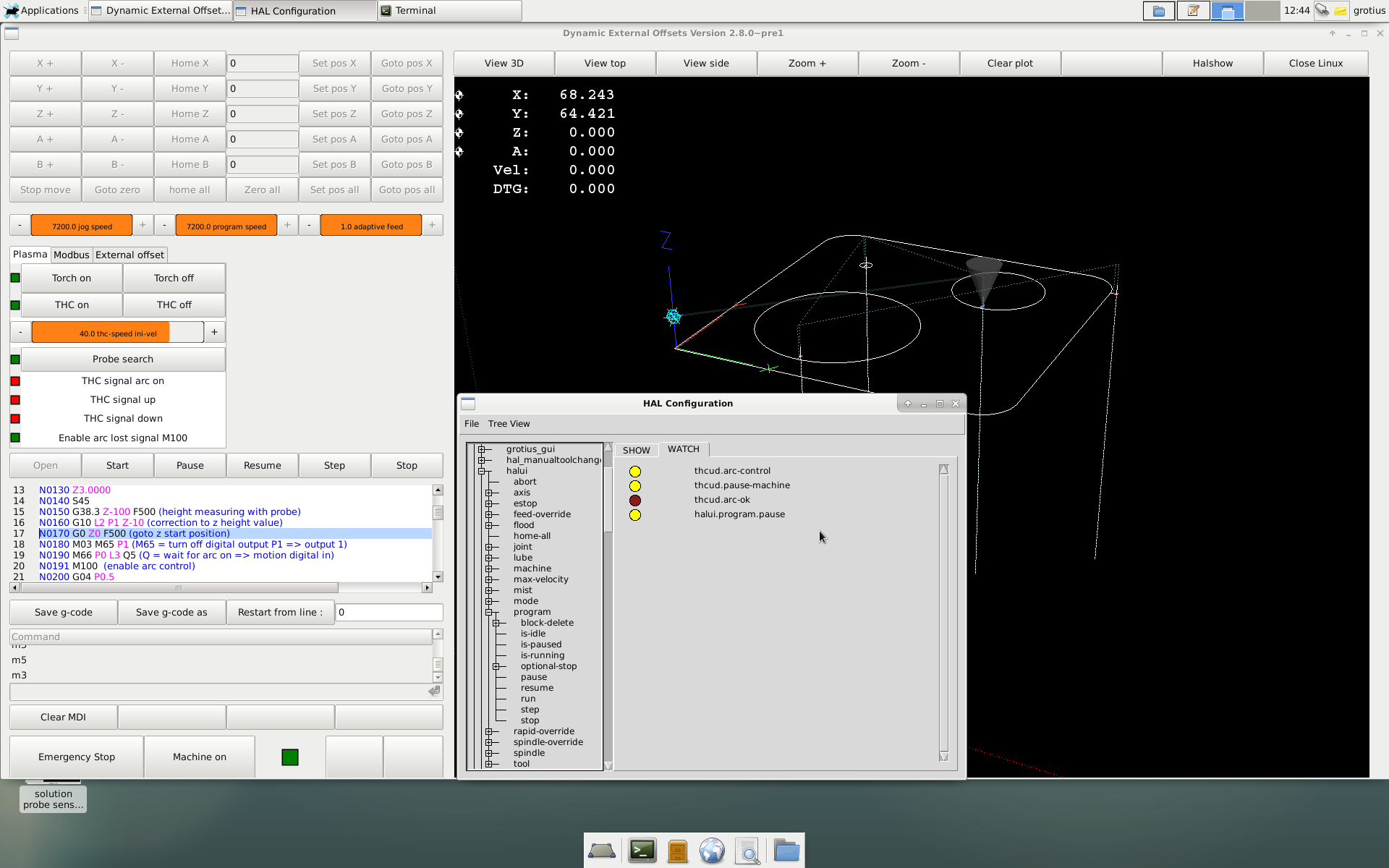
I have a solution that is working for pausing machine when arc transfer is lost. It depends on 4 files.
M100 (remove extension .txt and make executable)
M101
modified THCUD.comp
Postgui.hal ( this is simple : net pause thcud.pause-machine halui.program.pause
The M100 and M101 specifies the cutting path you exactly need in the program to trigger a arc transfer lost.
It begins to trigger after the waiting periode for stable arc.... And it ends at a m5. That was so difficult of this item.
Start triggering after stable arc....
Tjongejonge.... Why is uploading files so difficult here?
added pin in bit arc_control "M100 & M101 linking arc lost";
added pin out bit pause_machine "Pin for pausing";
For the thcud.comp i made a few modifications. Added pin in and pin out. Added
arc_control is the signal for the cutting path between the arc on waiting macro and the end of the cut.
!arc_ok means, no arc okey. The ! sign means it is not true.
Complete code :
Compiling thcud.comp : sudo halcompile --install thcud.comp
Rip location : src / hal / components
Orginal location : /usr/lib/linuxcnc/modules/
Don't forget if you have linux rip running .... To overwrite and replace the compiled comp file to the orginal linuxcnc directory")
Just for fun, to keep everyone here in good shape :

I have a solution that is working for pausing machine when arc transfer is lost. It depends on 4 files.
M100 (remove extension .txt and make executable)
M101
modified THCUD.comp
Postgui.hal ( this is simple : net pause thcud.pause-machine halui.program.pause
The M100 and M101 specifies the cutting path you exactly need in the program to trigger a arc transfer lost.
It begins to trigger after the waiting periode for stable arc.... And it ends at a m5. That was so difficult of this item.
Start triggering after stable arc....
Tjongejonge.... Why is uploading files so difficult here?
added pin in bit arc_control "M100 & M101 linking arc lost";
added pin out bit pause_machine "Pin for pausing";
For the thcud.comp i made a few modifications. Added pin in and pin out. Added
if(torch_on && arc_control && !arc_ok){ // pause machine
            pause_machine = 1;
        }
        if(!torch_on){ // pause machine
            pause_machine = 0;
        }
arc_control is the signal for the cutting path between the arc on waiting macro and the end of the cut.
!arc_ok means, no arc okey. The ! sign means it is not true.
Complete code :
component thcud "Torch Height Control Up/Down Input";

description
"""
Torch Height Control
This THC takes either an up or a down input from a THC

If enabled and torch is on and X + Y velocity is within tolerance of set speed
allow the THC to offset the Z axis as needed to maintain voltage.

If enabled and torch is off and the Z axis is moving up remove any correction
at a rate not to exceed the rate of movement of the Z axis.

If enabled and torch is off and there is no correction
pass the Z position and feed back untouched.

If not enabled pass the Z position and feed back untouched.

Typical Physical Connections using a Parallel Port
.br
Parallel Pin 12 <= THC controller Plasma Up
.br
Parallel Pin 13 <= THC controller Plasma Down
.br
Parallel Pin 15  <= Plasma Torch Arc Ok Signal
.br
Parallel Pin 16 => Plasma Torch Start Arc Contacts

HAL Plasma Connections
.br
net torch-up thcud.torch-up <= parport.0.pin-12-in
.br
net torch-down thcud.torch-down <= parport.0.pin-13-in
.br
net torch-on motion.spindle-on => parport.0.pin-16-out (start the arc)
.br
net arc-ok thcud.arc-ok <= motion.digital-in-00 <= parport.0.pin-15-in (arc ok signal)

HAL Motion Connections
.br
net requested-vel thcud.requested-vel <= motion.requested-vel
.br
net current-vel thcud.current-vel <= motion.current-vel

Pyvcp Connections
In the xml file you need something like:

  <pyvcp>
  <checkbutton>
    <text>"THC Enable"</text>
    <halpin>"thc-enable"</halpin>
  </checkbutton>
  </pyvcp>

Connect the Pyvcp pins in the postgui.hal file like this:

net thc-enable thcud.enable <= pyvcp.thc-enable


""";

author "The real John Thornton, i think it is him B) ";

license "GPLv2 or greater";

option singleton yes;

// Input Pins
pin in bit torch_up "Connect to an input pin";
pin in bit torch_down "Connect to input pin";
pin in float current_vel "Connect to motion.current-vel";
pin in float requested_vel "Connect to motion.requested-vel";
pin in bit torch_on "Connect to motion.spindle-on";
pin in bit arc_ok "Arc Ok from Plasma Torch";
pin in bit enable "Enable the THC, if not enabled Z position is passed through";
pin in float z_pos_in "Z Motor Position Command in from axis.n.motor-pos-cmd";
pin in bit arc_control "M100 & M101 linking arc lost";

// Output Pins
pin out float z_pos_out "Z Motor Position Command Out";
pin out float z_fb_out "Z Position Feedback to Axis";
pin out float cur_offset "The Current Offset";
pin out bit vel_status "When the THC thinks we are at requested speed";
pin out bit removing_offset "Pin for testing";
pin out bit pause_machine "Pin for pausing";

// Parameters
param rw float velocity_tol "The deviation percent from planned velocity";
param rw float correction_vel "The Velocity to move Z to correct";

// Global Variables
variable float offset;
variable float last_z_in;

function _;

;;

#include "rtapi_math.h"

FUNCTION(_) {
    if(enable){

        if(torch_on && arc_control && !arc_ok){ // pause machine
            pause_machine = 1;
        }
        if(!torch_on){ // pause machine
            pause_machine = 0;
        }

        float min_velocity = requested_vel -(requested_vel*(velocity_tol*0.01));
        if(current_vel > 0 && current_vel >= min_velocity){vel_status = 1;}
        else {vel_status =0;}


        if(torch_on && arc_ok && vel_status){ // allow correction
            if(torch_down){
                offset -= correction_vel;
            }
            if(torch_up){
                offset += correction_vel;
            }
            last_z_in = 0;

        }

        if(!torch_on){ // remove any offset
            float z_diff;
            z_diff = z_pos_in - last_z_in;
            if(z_diff > 0 && offset != 0){ // torch is moving up
                removing_offset = 1;
                if(offset > 0){ // positive offset
                    if(offset > z_diff){ // remove some
                        offset -= z_diff;
                    }
                    else {offset = 0;}
                }
                if(offset < 0){ // negative offset
                    if(offset < z_diff){ // remove some
                        offset += z_diff;
                    }
                    else {offset = 0;}
                }
            }
            else {removing_offset = 0;}
            last_z_in = z_pos_in;
        }
        z_pos_out = z_pos_in + offset;
        z_fb_out = z_pos_in; // keep axis motor position fb from being confused
    }
    if(!enable){
        z_pos_out = z_pos_in;
        z_fb_out = z_pos_in; // keep axis motor position fb from being confused
    }


}
Compiling thcud.comp : sudo halcompile --install thcud.comp
Rip location : src / hal / components
Orginal location : /usr/lib/linuxcnc/modules/
Don't forget if you have linux rip running .... To overwrite and replace the compiled comp file to the orginal linuxcnc directory
Just for fun, to keep everyone here in good shape :
Last edit: 14 Jul 2018 18:17 by Grotius.
Please Log in or Create an account to join the conversation.
- rodw
-
- Offline
- Platinum Member
-
Less
More
- Posts: 12038
- Thank you received: 4108
15 Jul 2018 08:42 #114202
by rodw
Replied by rodw on topic FPGA (field programmable gate array) programmed for linuxcnc motion
Grotius, thats great you solved that. I have to put all of these pieces together in my config soon.
I think I'll add a post in the plasma section linking to this post as its got some very useful info in it now.
I think I'll add a post in the plasma section linking to this post as its got some very useful info in it now.
Please Log in or Create an account to join the conversation.
- cmorley
- Offline
- Moderator
-

Less
More
- Posts: 7341
- Thank you received: 2164
15 Jul 2018 09:19 #114206
by cmorley
Replied by cmorley on topic FPGA (field programmable gate array) programmed for linuxcnc motion
motion.feed-inhibit may be helpful here - it will stop all motion if set true.
well it won't stop homing and it will finish a thread pass but I'm sure that is fine.
and it can't be inhibited with Gcode file feed-hold can.
Chris M
well it won't stop homing and it will finish a thread pass but I'm sure that is fine.
and it can't be inhibited with Gcode file feed-hold can.
Chris M
The following user(s) said Thank You: rodw
Please Log in or Create an account to join the conversation.
- LinuxCNC
- General LinuxCNC Questions
- FPGA (field programmable gate array) programmed for linuxcnc motion
Time to create page: 0.257 seconds