Wiring a chinese tool presetter.
- sliptonic
- Offline
- Premium Member
-

Less
More
- Posts: 132
- Thank you received: 22
01 Dec 2018 20:16 #121688
by sliptonic
Wiring a chinese tool presetter. was created by sliptonic
I picked up one of
these tool setters from eBay
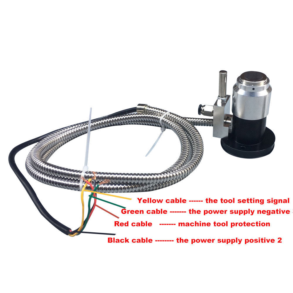
The price is right (USD $66) but the documentation is non-existent. Literally nothing in the box but the device itself. The only wiring info I have is this image from the listing and the limited specs. Has anyone used of these? Recommendations on wiring? (Mesa 5i25/7i77)
Specifications:
Model : Automatic tool setting
Color : Black + Silver
Material: Grinding 4S+ superhard alloy
Output mode: Normally open
Normally open specification technical parameters:
Output mode: A: NO (normally open)
Pre-stroke: about 0.5mm
Stroke: 5mm
Repeatability: 0.001mm (condition: operating speed 50-200mm/min)
Contact life: 3 million times
Protection structure: IP67
Contact force: 1.5N (installation status: vertical)
Contact material: super hard alloy
Housing material: grinding 4S
Contact rating: DC24V 20mA (MAX) (recommended value 10mA) resistance load
Cable: 5m oil resistant *6 core ,5.5 tensile strength 30N minimum bending radius R7
Protection tube: 2.5m minimum bending radius R25
LED light: normally open
Alarm signal when the stroke is exceeded
Output mode: B: NC (normally closed) (2.5mm from the measurement signal)
Contact rating: DC24V 100mA (resistance load)
Please Log in or Create an account to join the conversation.
- PCW
-

- Offline
- Moderator
-

Less
More
- Posts: 17959
- Thank you received: 5264
01 Dec 2018 20:59 - 01 Dec 2018 20:59 #121689
by PCW
Replied by PCW on topic Wiring a chinese tool presetter.
Just a WAG but similar devices seem to be like NO proximity switches
so you might try powering the device through the power wires (green and black)
and seeing what Yellow does when the device is tripped
I suspect Yellow will be grounded (connected to Green) when tripped
To connect this to a 7I77 input, you will need a pullup resistor from +24 to the Yellow wire+7I77 input
(suggest 2.4K to match their suggested load current)
PS love those Chinese color codes...
Last edit: 01 Dec 2018 20:59 by PCW.
Please Log in or Create an account to join the conversation.
- rodw
-

- Offline
- Platinum Member
-

Less
More
- Posts: 11990
- Thank you received: 4084
01 Dec 2018 21:20 #121691
by rodw
Replied by rodw on topic Wiring a chinese tool presetter.
So the input the yellow cable is attached to motion.probe−input
The red wire is used to sense if you go beyond the safe limit of travel so you don't smash the toolssetter. I think I'd attach it to a limit switch input (or OR2 it with an existing limit switch input). You might need to use the -not pin for that input.
By connecting it as a limit switch, you'll be able to jog off it with "Ignore Limits"
Just my idea, never used one.
The following user(s) said Thank You: Sadmeatball
Please Log in or Create an account to join the conversation.
- bevins
-
- Offline
- Platinum Member
-
Less
More
- Posts: 1942
- Thank you received: 338
02 Dec 2018 03:39 #121700
by bevins
Replied by bevins on topic Wiring a chinese tool presetter.
Why not fire a relay with the red wire and place it in series with Z limit. That way you could override and jog off.
Please Log in or Create an account to join the conversation.
- andypugh
-

- Offline
- Moderator
-
Less
More
- Posts: 19875
- Thank you received: 4642
06 Dec 2018 17:05 #121960
by andypugh
Replied by andypugh on topic Wiring a chinese tool presetter.
There is a pneumatic fitting on that toolsetter. What does that do?
Is there a tool-cleaning air blast feature?
Unlikely at the price, but maybe two of the wires operate an air solenoid valve?
Is there a tool-cleaning air blast feature?
Unlikely at the price, but maybe two of the wires operate an air solenoid valve?
Please Log in or Create an account to join the conversation.
- sliptonic
- Offline
- Premium Member
-
Less
More
- Posts: 132
- Thank you received: 22
06 Dec 2018 18:56 #121981
by sliptonic
Replied by sliptonic on topic Wiring a chinese tool presetter.
It's a port for the air blast. There's no solenoid to control, it's just the port plumbed up to the jet at the top of the metal feature.
Please Log in or Create an account to join the conversation.
- andypugh
-
- Offline
- Moderator
-
Less
More
- Posts: 19875
- Thank you received: 4642
06 Dec 2018 18:59 #121982
by andypugh
Replied by andypugh on topic Wiring a chinese tool presetter.
Makes sense.
I later read that there is an LED, so presumably that is why it needs power and gnd. I would hook it up and see what you see with a multimeter.
It might be that you need to use the DMM in voltage mode, or in continuity mode, to figure out if it is a switch or a voltage source.
I later read that there is an LED, so presumably that is why it needs power and gnd. I would hook it up and see what you see with a multimeter.
It might be that you need to use the DMM in voltage mode, or in continuity mode, to figure out if it is a switch or a voltage source.
Please Log in or Create an account to join the conversation.
- sliptonic
- Offline
- Premium Member
-
Less
More
- Posts: 132
- Thank you received: 22
27 Jan 2019 21:15 #124990
by sliptonic
Replied by sliptonic on topic Wiring a chinese tool presetter.
I finally had some time today to get back to this. Here's what I found so far:
Power it with the black/green makes sense. The specs say there's an LED but I certainly don't see one.
When powered, the red goes high when it exceeds the stroke. So that makes sense too.
Yellow is NC to green/ground and opens at the touch.
Does that make sense?
Power it with the black/green makes sense. The specs say there's an LED but I certainly don't see one.
When powered, the red goes high when it exceeds the stroke. So that makes sense too.
Yellow is NC to green/ground and opens at the touch.
Does that make sense?
Please Log in or Create an account to join the conversation.
- yoshimitsuspeed
- Offline
- Premium Member
-
Less
More
- Posts: 98
- Thank you received: 0
29 Jan 2019 06:48 #125133
by yoshimitsuspeed
Replied by yoshimitsuspeed on topic Wiring a chinese tool presetter.
Did you ever get this working? I have been wanting to do this but never got around to it. If you have had success with this one I'd be pretty tempted to order one.
How hard is it to set up the machine to include using this in it's operation?
How hard is it to set up the machine to include using this in it's operation?
Please Log in or Create an account to join the conversation.
- sliptonic
- Offline
- Premium Member
-
Less
More
- Posts: 132
- Thank you received: 22
29 Jan 2019 13:42 #125166
by sliptonic
Replied by sliptonic on topic Wiring a chinese tool presetter.
I'm pretty close but not there yet. When it comes to working with the 'angry pixies' I'm really terrible. Actual electronics frustrates and confuses me.
As noted above, if I wire: Green -> Ground, Black -> 24V, Red -> Input
I get a signal on the input when the switch is pushed all the way down in the travel. I assume this is the 'machine protection' to act like a limit switch.
I don't get a similar signal on yellow though. Instead, yellow seems to be normally closed with green and opens at the first touch.
I suppose I could wire green->24V Yellow->Input and ignore the other two but I don't understand how to make both circuits work at the same time.
For about $65 bucks, the quality looks pretty nice. It's solidly built. No detectable play in the switch mechanism but I don't see any LED as noted in the spec.
The following user(s) said Thank You: Sadmeatball
Please Log in or Create an account to join the conversation.
Time to create page: 0.142 seconds