Wiring a chinese tool presetter.
- Mike_Eitel
-

- Offline
- Platinum Member
-

Less
More
- Posts: 1052
- Thank you received: 183
04 May 2019 20:33 #132768
by Mike_Eitel
Replied by Mike_Eitel on topic Wiring a chinese tool presetter.
Hi
.......
Between your points 19x7-2 and 19x7-9
24VDC regardless whether the tool setter is depressed or happy.
......
BAD. You will never get a change on io. First there must be a change!!
Measure if 3a1-5 is on gnd level.
.......
Between your points 19x7-2 and 19x7-9
24VDC regardless whether the tool setter is depressed or happy.
......
BAD. You will never get a change on io. First there must be a change!!
Measure if 3a1-5 is on gnd level.
Please Log in or Create an account to join the conversation.
- andypugh
-

- Offline
- Moderator
-

Less
More
- Posts: 19875
- Thank you received: 4642
06 May 2019 18:14 #132983
by andypugh
Replied by andypugh on topic Wiring a chinese tool presetter.
Do you have the same gauge as the original poster (Sliptonic?)
If so, then you need to power the sensor with 24V and then the yellow output wire will change state as the switch is pressed.
So, you need both the wiring you show (where the switch is yellow to ground) and the 24V + GND power supply for the sensor itself.
If so, then you need to power the sensor with 24V and then the yellow output wire will change state as the switch is pressed.
So, you need both the wiring you show (where the switch is yellow to ground) and the 24V + GND power supply for the sensor itself.
Please Log in or Create an account to join the conversation.
- RotarySMP
-

- Offline
- Platinum Member
-
Less
More
- Posts: 1627
- Thank you received: 595
06 May 2019 19:47 - 06 May 2019 19:59 #132994
by RotarySMP
Replied by RotarySMP on topic Wiring a chinese tool presetter.
Hello Andy,
no mine is a bit different. You can see it and its schematic here.
It seems to be two separate circuits for the two switches.
Mark
no mine is a bit different. You can see it and its schematic here.
It seems to be two separate circuits for the two switches.
Mark
Last edit: 06 May 2019 19:59 by RotarySMP.
Please Log in or Create an account to join the conversation.
- andypugh
-
- Offline
- Moderator
-
Less
More
- Posts: 19875
- Thank you received: 4642
07 May 2019 18:46 #133076
by andypugh
Replied by andypugh on topic Wiring a chinese tool presetter.
If it is just two physical switches then I think you would just wire the switches between 24V and a 7i76(?) input pin.
Please Log in or Create an account to join the conversation.
- RotarySMP
-
- Offline
- Platinum Member
-
Less
More
- Posts: 1627
- Thank you received: 595
07 May 2019 19:49 #133084
by RotarySMP
Replied by RotarySMP on topic Wiring a chinese tool presetter.
The instructions include a limitation on not more than 20mA current. Wouldn't shorting 24VDC directly though this switch to a 7i77 input pin exceed that current limit?
Please Log in or Create an account to join the conversation.
- andypugh
-
- Offline
- Moderator
-
Less
More
- Posts: 19875
- Thank you received: 4642
07 May 2019 20:54 #133093
by andypugh
Replied by andypugh on topic Wiring a chinese tool presetter.
Digital inputs are high impedance. They have to be ur nothing could ever change their voltage level.
If you want to be sure, use a multimeter in current mode to connect an input to +24V. You should see a state-change in the input and a few mA of current.
If you want to be sure, use a multimeter in current mode to connect an input to +24V. You should see a state-change in the input and a few mA of current.
Please Log in or Create an account to join the conversation.
- RotarySMP
-
- Offline
- Platinum Member
-
Less
More
- Posts: 1627
- Thank you received: 595
08 May 2019 06:34 #133110
by RotarySMP
Replied by RotarySMP on topic Wiring a chinese tool presetter.
Thanks for that desciption.
Please Log in or Create an account to join the conversation.
- MRx
- Offline
- Senior Member
-

Less
More
- Posts: 54
- Thank you received: 9
16 Jan 2021 08:23 - 16 Jan 2021 08:36 #195521
by MRx
Replied by MRx on topic Wiring a chinese tool presetter.
Just for the record, my tool is using a KAQY214S solid state mosfet inside. Now you can look up the detailed specs yourself, it's easy to disassemble the entire unit, there's not much technology inside
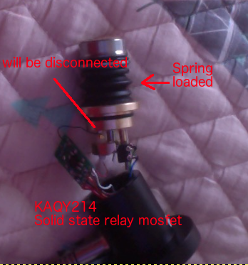
I think 2 components which look like a capacitor are just Fuses / PTC fuses maybe.
I think 2 components which look like a capacitor are just Fuses / PTC fuses maybe.
Attachments:
Last edit: 16 Jan 2021 08:36 by MRx.
Please Log in or Create an account to join the conversation.
- hoffb77
-

- Offline
- Senior Member
-
Less
More
- Posts: 53
- Thank you received: 21
03 Feb 2021 01:49 #197504
by hoffb77
Replied by hoffb77 on topic Wiring a chinese tool presetter.
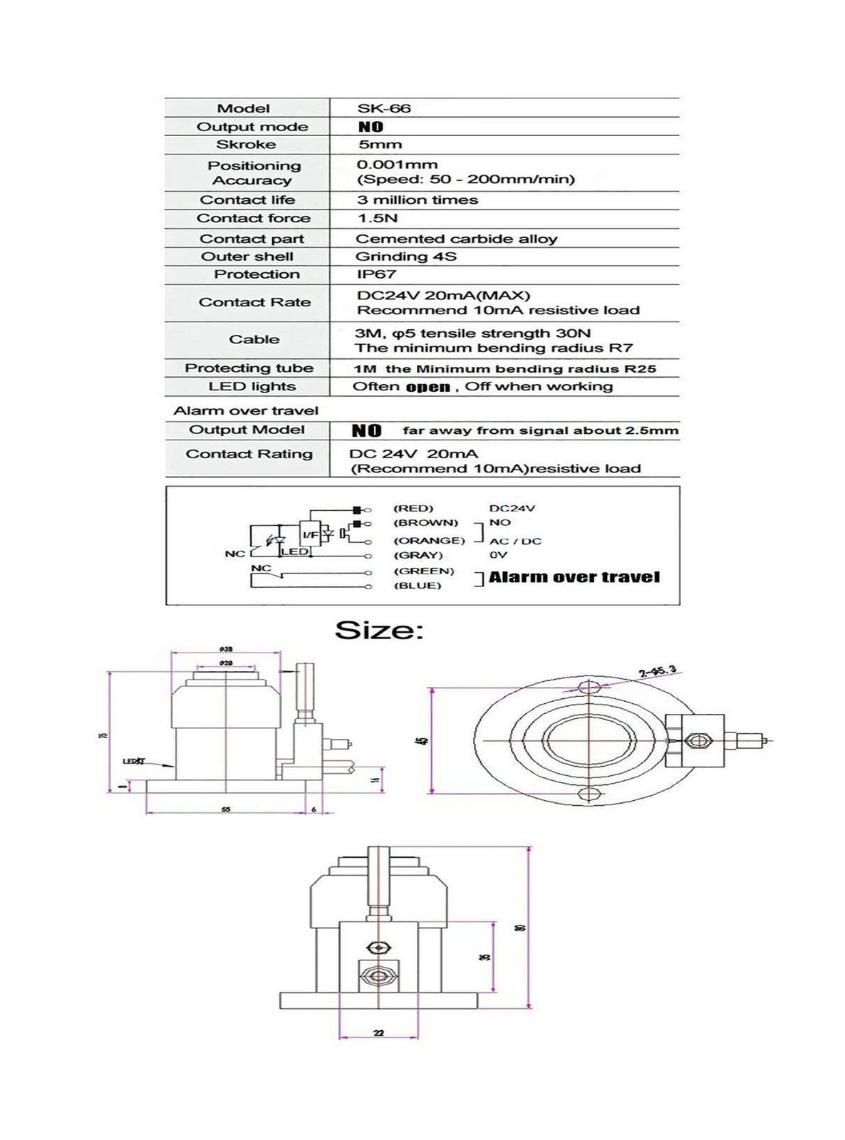
This is the schematic on Amazon.
It has two switches. One is NO the other is NC.
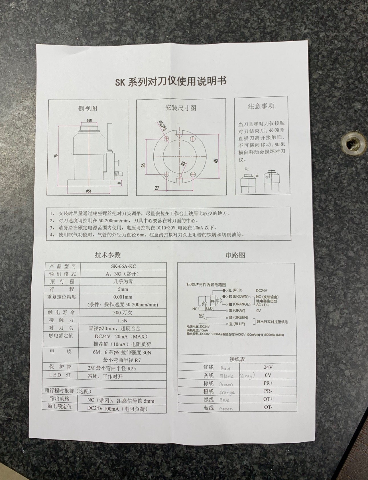
The schematic that came with the setter is the same but a bit more descriptive concerning the contacts.
60v DC 100ma / 60v AC 100ma- 500mw max
It has two switches. One is NO the other is NC.
The schematic that came with the setter is the same but a bit more descriptive concerning the contacts.
60v DC 100ma / 60v AC 100ma- 500mw max
Attachments:
Please Log in or Create an account to join the conversation.
- hoffb77
-
- Offline
- Senior Member
-
Less
More
- Posts: 53
- Thank you received: 21
03 Feb 2021 02:02 #197506
by hoffb77
Dont look at it to long.......
Replied by hoffb77 on topic Wiring a chinese tool presetter.
Dont look at it to long.......
Attachments:
Please Log in or Create an account to join the conversation.
Time to create page: 0.283 seconds