Wiring a chinese tool presetter.
- andypugh
-

- Offline
- Moderator
-

- Posts: 19875
- Thank you received: 4642
I don't get a similar signal on yellow though. Instead, yellow seems to be normally closed with green and opens at the first touch.
Exactly as PCW predicted?
What is your input interface? If it is a parallel port then you can connect the yellow wire direct to a parport pin (as these are pulled up and can be switched by connecting to gnd).
If it's a proximity switch inside then that will kill it.I suppose I could wire green->24V Yellow->Input and ignore the other two but I don't understand how to make both circuits work at the same time.
Does the red wire go to +24 when the switch is pressed all the way and is OC otherwise?
Please Log in or Create an account to join the conversation.
- sliptonic
- Offline
- Premium Member
-

- Posts: 132
- Thank you received: 22
Wiring into a 7i77.
Yes. The red goes to +24 when fully pressed.
Please Log in or Create an account to join the conversation.
- andypugh
-
- Offline
- Moderator
-
- Posts: 19875
- Thank you received: 4642
Please Log in or Create an account to join the conversation.
- sliptonic
- Offline
- Premium Member
-
- Posts: 132
- Thank you received: 22
I connected it with an or2 with my touch probe. I also connected the 'machine protect' connection with an or2 to the Zmin limit switch as rodw suggested.
Seems to be working perfect. Now I just need to figure out my workflow for setting tool length offsets and touching off.
Thanks guys.
Please Log in or Create an account to join the conversation.
- DeckelHead
- Offline
- Elite Member
-

- Posts: 166
- Thank you received: 2
[edit: hmmm, your one has fewer wires, and mine definitely has an LED, so apparently the units are different... Have you gotten the software part of the preset working? I'm curious how the whole 'insert a new tool, go and preset it so you verify you have the right tool in' part gets added to LinuxCNC and works]
Anyhow, here you go....
Please Log in or Create an account to join the conversation.
- pl7i92
-

- Offline
- Platinum Member
-

- Posts: 1872
- Thank you received: 358
as a G91 move
BEST practice for me in Education here is to get a TOOL with given Max length 100.00mm here RIM 10mm it is exactly the 100 +- 0,01mm
tool number 100 this is the tool that never changend the holder
WE set this to Cordinate system P6 G59 as the Tool ZERO point
then you simply call G59 Tx M6 (with Hx length set to Zero)
touch down
and enter the Different to 100 to the Tool table
THIS can be automatet as G10 L1 Px Z[100-#5323]
use a ngc to make all this to your need
Button that calls this ngc
Please Log in or Create an account to join the conversation.
- RotarySMP
-

- Offline
- Platinum Member
-
- Posts: 1627
- Thank you received: 595
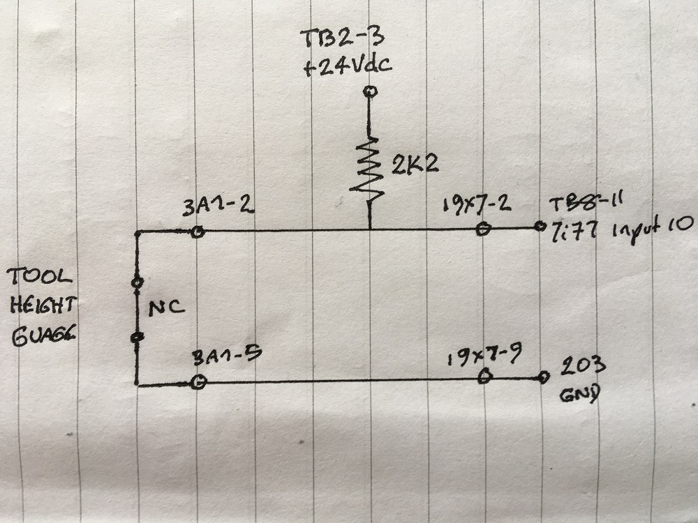
When I check it with HALShow, the attached 7i77 pin stays high, even when the button is pushed. I would appreciate some suggestions in trouble shooting this.
Mark
Attachments:
Please Log in or Create an account to join the conversation.
- Mike_Eitel
-

- Offline
- Platinum Member
-
- Posts: 1052
- Thank you received: 183
What show measurement betwee your points 19x7-2 and 19x7-9
Is your 7i72 field connected to 203 gnd
What happens on io pin of 7i72
Mike
Please Log in or Create an account to join the conversation.
- J Green
- Offline
- Elite Member
-
- Posts: 164
- Thank you received: 24
I think Mike E has made some good suggestions .
Only thing I can think of is to temporary replace the Tool Setter with a clip lead to get it out of the equation.
Really like the idea of using a volt meter to measure voltage between 3A1-5 and 7i72 s 24volt ground return at the Bd.
Is this the same 24 volt that powers the Exe Board ?
What is the maximum input voltage and amp for a 7i72 Board input?
Try measuring voltage across the 2K ohm resistor using a clip lead to simulate the disconnected Tool Setters Normally Closed contact.
Check for same but opposite results at the 7i72 Bd terminals.
Hope you are only missing a ground connection
Shorting the 24 volt to ground is considered "bad form"

Bob
Please Log in or Create an account to join the conversation.
- RotarySMP
-
- Offline
- Platinum Member
-
- Posts: 1627
- Thank you received: 595
Is your 7i72 field connected to 203 gnd?
Good pick up. No. The MAHO has two 24VDC circuits. One is always powered and the other dropped by the E-Stop. I have the 7i77 on the always powered circuit between 204 (+24VDC) and 201 (GND). So I have now changed my tool setter ground from 203, to 201 (well actually to a vacant PE terminal connected to 201, as I had no 201 terminals free. Bad practice?
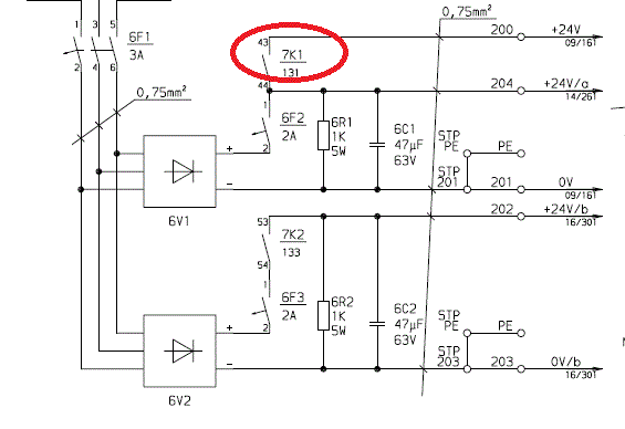
Ignore the red circle around the relay. I recycled this image from another discusion. I retested it after changing the ground, but still get no joy. hm2-5i25.0.7i77.0.0.input-10 remains high whether I depress the tool setter or not.
Between your points 19x7-2 and 19x7-9
24VDC regardless whether the tool setter is depressed or happy.
What happens on io pin of 7i72
Do you mean what does the HALShow of hm2-5i25.0.7i77.0.0.input-10 indicate? Always high.
Only thing I can think of is to temporary replace the Tool Setter with a clip lead to get it out of the equation.
Did that. Even with the tool setter removed (Open circuit between 3A1-2 and 3A1-5, the HALshow shows the pin high.
Is this the same 24 volt that powers the Exe Board ?
Yes, TB2-3 is one of the 7i77's Field power connections, so I am taking the same power as the board.
Shorting the 24 volt to ground is considered "bad form.
Thanks Bob, what would be the correct way to do it?
What is the maximum input voltage and amp for a 7i72 Board input?
From the MESA 7i77 manual...
48 points of isolated field I/O are provided for general control use including limit
switch, control panel inputs, coolant enable and tool changer control outputs. Isolated I/O
includes 32 sinking inputs and 16 sourcing outputs. Inputs can sense 5V to 32V signals
and the outputs can switch 5V through 28V signals. Maximum output load is 300 mA.
Outputs are short circuit protected. Field I/O is powered by an isolated 10-32V field power
source.
Try measuring voltage across the 2K ohm resistor using a clip lead to simulate the disconnected Tool Setters Normally Closed contact.
Differcult. I heat shrinked the node with the 2k2 resister and it's branches, and the connector is some mil spec pin insertion DSub which a work colleagues dead Dad borrowed from his French military Tank factory a couple of decades ago. The connector is well insulated from prying multimeters....
... but for Bob, we can abuse it till we get an exposed wire to probe. I measure 2.4VDC across the resister.
Mark
Please Log in or Create an account to join the conversation.