Getting arc pierces on lead in on inside cuts
- TexasCNC
- Offline
- Platinum Member
-

Less
More
- Posts: 373
- Thank you received: 10
21 Feb 2020 03:30 #158084
by TexasCNC
Getting arc pierces on lead in on inside cuts was created by TexasCNC
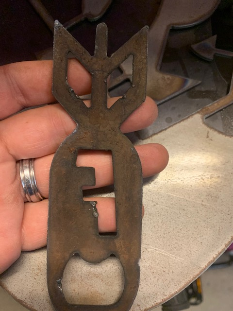
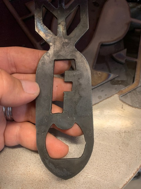
I am getting arc marks on my lead ins on my cuts I have checked the kerf width on sheetcam and on the plasma config on the axis tab not sure what else to check I have new consumables do i need to change the kerf width to compensate but I had done that but didnt see a difference. Any info out there for me to check?
Attachments:
Please Log in or Create an account to join the conversation.
- rodw
-

- Offline
- Platinum Member
-

Less
More
- Posts: 11701
- Thank you received: 3954
21 Feb 2020 06:59 #158090
by rodw
Replied by rodw on topic Getting arc pierces on lead in on inside cuts
What plasma cutter and what thickness material?
What amperage?
What kind of leadin?
I was wondering if your velocity and acceleration is too slow if you were doing a perpendicular lead in. (Which is what I use)
What amperage?
What kind of leadin?
I was wondering if your velocity and acceleration is too slow if you were doing a perpendicular lead in. (Which is what I use)
Please Log in or Create an account to join the conversation.
- bbsr_5a
- Offline
- Platinum Member
-

Less
More
- Posts: 544
- Thank you received: 105
21 Feb 2020 08:26 - 21 Feb 2020 08:59 #158099
by bbsr_5a
Replied by bbsr_5a on topic Getting arc pierces on lead in on inside cuts
Attachments:
Last edit: 21 Feb 2020 08:59 by bbsr_5a. Reason: image
Please Log in or Create an account to join the conversation.
- tommylight
-

- Away
- Moderator
-

Less
More
- Posts: 21253
- Thank you received: 7253
21 Feb 2020 11:38 #158119
by tommylight
Replied by tommylight on topic Getting arc pierces on lead in on inside cuts
Are you sure that is caused at the start of the cut and not at the end? The ends tend to make a wide divot, but form the picture it looks like you added lead ins and compensated lead in from the wrong side so it is cutting into material and then backing off.
That can also be caused when the inner part falls off and the arc widens chasing the falling piece.
That can also be caused when the inner part falls off and the arc widens chasing the falling piece.
Please Log in or Create an account to join the conversation.
- TexasCNC
- Offline
- Platinum Member
-

Less
More
- Posts: 373
- Thank you received: 10
21 Feb 2020 21:52 #158155
by TexasCNC
Replied by TexasCNC on topic Getting arc pierces on lead in on inside cuts
Well I tried doing lead outs but the torch looses arc then errors out that it lost arc I had brought this up to phill but he said that the post processor he had me load up on sheetcam didn’t show any issues as to why it was doing that. I tried messing with kerf width but that doesn’t seem to help at all. And I am not sure if it’s in the beginning of the cut or end though.
Please Log in or Create an account to join the conversation.
- TexasCNC
- Offline
- Platinum Member
-

Less
More
- Posts: 373
- Thank you received: 10
21 Feb 2020 21:54 #158156
by TexasCNC
Replied by TexasCNC on topic Getting arc pierces on lead in on inside cuts
Thermal Dynamics CM52
14g steel
40 amps
Arc lead in
And I tried diff ones but still seems to not working
14g steel
40 amps
Arc lead in
And I tried diff ones but still seems to not working
Please Log in or Create an account to join the conversation.
- TexasCNC
- Offline
- Platinum Member
-

Less
More
- Posts: 373
- Thank you received: 10
22 Feb 2020 07:49 #158176
by TexasCNC
Replied by TexasCNC on topic Getting arc pierces on lead in on inside cuts
Changed my kerf width from 0.059 to 0.03 and I can still see the arc marks it makes. Then changed it to 0.07 still the same. I went to ad I measured the kerf width of a test line I made and its close to being 0.04 inches thats why I was putting those numbers to test. I slowed down the THC and I raised the the speed on my cuts as well. Not sure what else to check to get a cleaner cut to get the kerf not to indent the cuts where it starts. I cant do lead outs cause it looses the arc on the inside the cuts so it only has to be lead ins.
Please Log in or Create an account to join the conversation.
- phillc54
-

- Offline
- Platinum Member
-

Less
More
- Posts: 5711
- Thank you received: 2093
22 Feb 2020 08:19 - 22 Feb 2020 08:56 #158177
by phillc54
Replied by phillc54 on topic Getting arc pierces on lead in on inside cuts
Kerf Width only has an effect in PlasmaC if you are using G41.2 or G42.1 for cutter compensation. It will change the whole part size.
Normally SheetCam would compensate for kerf width and not use cutter compensation.
Could you post the GCode file you are having trouble with and I will have a look tomorrow.
Edit: could you also post a screenshot of the Config and Run panel settings you use for that job.
Normally SheetCam would compensate for kerf width and not use cutter compensation.
Could you post the GCode file you are having trouble with and I will have a look tomorrow.
Edit: could you also post a screenshot of the Config and Run panel settings you use for that job.
Last edit: 22 Feb 2020 08:56 by phillc54.
Please Log in or Create an account to join the conversation.
- tommylight
-

- Away
- Moderator
-

Less
More
- Posts: 21253
- Thank you received: 7253
22 Feb 2020 08:56 #158182
by tommylight
Replied by tommylight on topic Getting arc pierces on lead in on inside cuts
Those divots are not made at the start of the cut.
They look likely to be made by lead in moving outside of the cut line or from overburn when the plasma is switched off.
Another thing that might cause that at the end is, the step per milimeter or inch is way to low, so for short movements the motors actually stay in one place, causing that overburn. I really doubt it is the latter as the sloped cuts look OK.
Please Log in or Create an account to join the conversation.
- bbsr_5a
- Offline
- Platinum Member
-

Less
More
- Posts: 544
- Thank you received: 105
22 Feb 2020 09:48 #158185
by bbsr_5a
Replied by bbsr_5a on topic Getting arc pierces on lead in on inside cuts
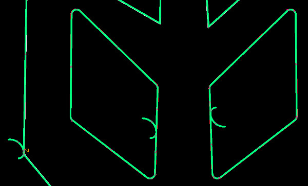
on sheetcam you can look on the path if it is on the right side
and you can do the CONTOUR button and Right mouse on the outer contour
move to new layer and work your way to the contours if they are not in your way orderd to be Inside outside compatible to eatch other
likwise Rhino DXF does lots of path cahanges while Qcad orders/sort/direct all the same way
and you can do the CONTOUR button and Right mouse on the outer contour
move to new layer and work your way to the contours if they are not in your way orderd to be Inside outside compatible to eatch other
likwise Rhino DXF does lots of path cahanges while Qcad orders/sort/direct all the same way
Please Log in or Create an account to join the conversation.
Time to create page: 0.265 seconds


