- LinuxCNC
- General LinuxCNC Questions
- How would you design a real time application for cnc control in c / c++ ???
How would you design a real time application for cnc control in c / c++ ???
- Grotius
-
 Topic Author
- Offline
- Platinum Member
-

- Posts: 2419
- Thank you received: 2345
I tried your light sabre example. It comes back exact at the position.
One explanation for this is that the KDL uses a target point for FK and IK (forward kinematic / inverse kinematics).
You give up your target point + target euler angles.
You say i want to go to Point { x500,y500,z500 } with euler angles { 0,0,0,} it will simply return the joint values in double precision. And it will say if the IK was succesfull. When it return's a error, you know you crossed joint limits or something like that.
If you look at the source code of lcnc gensterkins, you see multiple comments like : fixme.
The lcnc gensterkin code is not really a mature code, and it's bad commented. It's commented like a closed source.
Just a example taken from the lcnc gensterkins source code, its a section of compute joint forward :
/* Jv */
	go_matrix_vector_cross(&Jw, P_ip1_i, &scratch);
	go_matrix_matrix_add(&Jv, &scratch, &scratch);
	go_matrix_matrix_mult(&R_i_ip1, &scratch, &Jv);
	Jv.el[0][col] = 0, Jv.el[1][col] = 0, Jv.el[2][col] = (GO_QUANTITY_LENGTH == link_params[col].quantity ? 1 : 0);
	/* Jw */
	go_matrix_matrix_mult(&R_i_ip1, &Jw, &Jw);
	Jw.el[0][col] = 0, Jw.el[1][col] = 0, Jw.el[2][col] = (GO_QUANTITY_ANGLE == link_params[col].quantity ? 1 : 0);
	if (GO_LINK_DH == link_params[col].type) {
	    go_dh_pose_convert(&link_params[col].u.dh, &pose);
	} else if (GO_LINK_PP == link_params[col].type) {
	    pose = link_params[col].u.pp.pose;
	} else {
	    return GO_RESULT_IMPL_ERROR;
	}
	go_pose_pose_mult(T_L_0, &pose, T_L_0);
    }
What do you think if you see this above code?
If you ask me..
This is a very bad piece of code. There are no comment's. There is almost nothing to understand. So very bad coded in my opinion,
with respect to the maker, because some parts of gensterkins seems to work.
My advise is don't invest any time in this, it will bring you nowhere.
Mind you my programming capabilities are very limited. But I don't even know how to solve the problem theoretically using euler angles
That's no problem. You don't have to know everything. You just have to use the right tools. And if nobody points you too the right stuff, you can have a hard time to find out how things work.
Mind you I probably would have to code that in C or C++ to be handled in realtime space.
Things are not as difficult as you might think. For FK and IK interpolation the servo threat is fast enough, It may even be slower. Then you have the waypoints. The stepgen can solve the steps between the waypoints in the base-threat. And there you go !
The interpolation between the waypoints, can be simple like : lineair interpolation, but can be cubic spline also. It's how you set it up.
This is a very compact code, and can perform fast interpolation. Why this? Because you don't wanna do a IK every 0.1mm of the path.
An IK that has waypoints for every mm is good for the most apps.
@ Aleksamc,
Sorry, i have no intention to make a video. I think other's can make a review video when the program works and is published.
It will take some time to finish the program.
Please Log in or Create an account to join the conversation.
- Aciera
-

- Offline
- Administrator
-

- Posts: 4621
- Thank you received: 2045
I tried your light sabre example. It comes back exact at the position.
Ah, that sounds promising. Your set up is still a bit difficult to grasp for me though, particulary how it interfaces with the gcode. So let me try to explain what I am looking for by pointing out how it works on my running Mitsubishi setup:
If you feel like it you can have a look at the different jog operation modes (from page 32 onward):
suport.siriustrading.ro/02.DocArh/07.RI/...8655-L%20(05.11).pdf
More on the coordinate systems (Page 157 and onward, particularly 162,162,164):
www.allied-automation.com/wp-content/upl...s-and-Operations.pdf
Basically the question is how do I define what my tool looks like that is attached to the robots flange and how do I tell the KDL which coordinate system I want the move to be performed in. So the gcode will need to "emulate" the robot programming language's capability to switch between the different coordinate systems and thus between different kinematics. In LinuxCNC my idea was to use the switchkins capabilities to switch from joint mode to cartesian world mode with the zero point on the bottom of the robots base and use remaps like G90.1 to specify a move in tool coordinates. How would this look in your scenario?
What I am trying to avoid is to have to set up everything in a virtual environment and get the joint positions from that so I can then create the necessary movments in a program. There needs to be a jogging possibility in the different coordinate systems and the capability to save the joint and/or cartesian positions of the current posture of the arm. So in effect a teach in mode where a pick up position can be defined and then a drop position or a the position where the chuck of a lathe grabs the part in the gripper.
I'm not sure if this actually makes any sense to you.
I tried to get an understanding of it but as you said there is VERY little to go by except to totally reverse engineer the whole thing. Which is a shame as I am sure it was quite an effort to put that code together. But it works and does to a large extent what it is supposed to do. I believe it uses the inverse Jacobian just like KDL. But there are some things that restrict it a bit. But since I'm a beggar when it comes to C programming I can't be a chooser.The lcnc gensterkin code is not really a mature code, and it's bad commented. It's commented like a closed source.
Please Log in or Create an account to join the conversation.
- Grotius
-
 Topic Author
- Offline
- Platinum Member
-

- Posts: 2419
- Thank you received: 2345
particulary how it interfaces with the gcode.
The purpose is to use the lcnc gcode infrastructure and motion handling to start with.
My program display's the ngc code as it is trough a tiny parser. But lcnc is doing the work.
If you feel like it you can have a look at the different jog operation modes
This is exactly the industry standard. I want to start the program with a minimal working example. For now that only including the
robot frame. The robot and the tools can be defined. The tool can rotate about it's centerpoint. But is not fully functional as it can
move in toolframe axis. Also workframe has to be integrated. This is all not very difficult.
to switch between the different coordinate systems and thus between different kinematics.
The kinematics are stay same for the robot.
If the gcode program uses a workframe, it will multiply the robot fk/ik by that workframe-matrix and apply some tool offsets to get there.
For now it's not available, but has to be coded.
to use the switchkins capabilities to switch from joint mode to cartesian world mode with the zero point on the bottom of the robots base and use remaps like G90.1 to specify a move in tool coordinates. How would this look in your scenario?
If you look at the last posted picture, you see already a tool offset. This is the first step to zero the gcode startpoint.
You know later on, it's like a workframe including the euler angels.
For this workframe and zero point for the gcode i will show a box with a trihedron to show what is going on. Its the same as in your pdf document.
There needs to be a jogging possibility in the different coordinate systems and the capability to save the joint and/or cartesian positions of the current posture of the arm.
Yes of course. The controls are already there. These controls are for jogging. They work very well. You don't have to switch between joint or cartesian mode. It will update each other on the spot.
The planning is to make a gui screen for each solution. This will keep the program very modulair. So every option is a widget with a gui.
A widget includes a source file and a header file and a gui (hmi window)
-Teach in
-Gcode
-Controls
-Hal connections
etc.
Now coding the automated hal connection's.
Please Log in or Create an account to join the conversation.
- Aciera
-

- Offline
- Administrator
-

- Posts: 4621
- Thank you received: 2045
Please Log in or Create an account to join the conversation.
- Grotius
-
 Topic Author
- Offline
- Platinum Member
-

- Posts: 2419
- Thank you received: 2345
I did the hal connections today and made a short video when it simulate a lcnc gcode.
Sinds there is no freedom of speech on youtube (not imporant for me, but for other users) i do it this way :
video
Please Log in or Create an account to join the conversation.
- Clive S
- Offline
- Platinum Member
-

- Posts: 2202
- Thank you received: 482
Please Log in or Create an account to join the conversation.
- tommylight
-

- Offline
- Moderator
-

- Posts: 21121
- Thank you received: 7216
Please Log in or Create an account to join the conversation.
- Aciera
-

- Offline
- Administrator
-

- Posts: 4621
- Thank you received: 2045
So I downloaded your git repo.
git clone git://github.com/grotius-cnc/Skynet_Robot_Control_Rtos_Ethercat.git KDL-devsudo apt-get install qtcreator
sudo apt-get install qt5-doc qtbase5-examples qtbase5-doc-html
sudo apt-get install qt5-default
[edit] also needed:
sudo apt-get install qtdeclarative5-devI installed the OpenCascade library:
libocct-visualization-7.3and the KDL library:
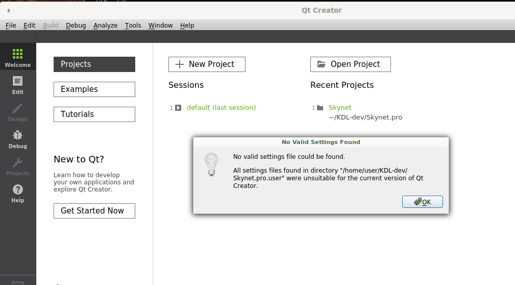
liborocos-kdl-devNow I try to open the Skynet project in Qt Creator but I get an error saying its missing a "valid settings file":
[edit]
Ok, I'm a step further by doing this:
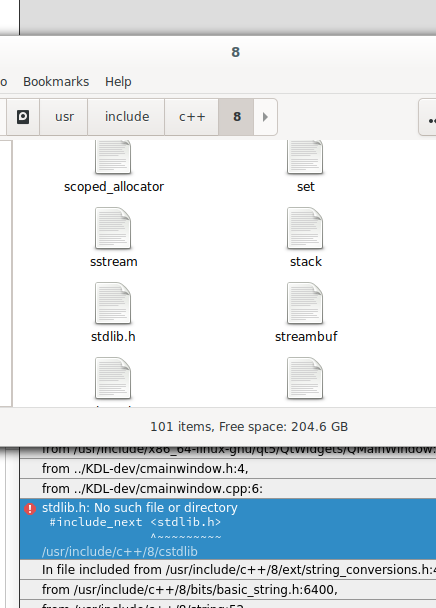
Go to Tools -> Options.... Select Build & Run on left. Open Kits tab. You should have Manual -> Desktop (default) line in list. Choose it. Now select something like Qt 5.5.1 in PATH (qt5) in Qt version combobox and click Apply button. From now you should be able to create, build and run empty Qt project.Now I get errors "stdlib.h: no such file or directory"
[edit2]
looks like I'm missing the folder /user/include/c++/8/stdlib
Thanks
Attachments:
Please Log in or Create an account to join the conversation.
- Grotius
-
 Topic Author
- Offline
- Platinum Member
-

- Posts: 2419
- Thank you received: 2345
Tody it's my mom's birthsday. Later on i will make some install steps for you. You better stop trying install now.
And you need to get the latest release off course !
I have to upload this first to git. Will let you know when it's ready.
I have integrated the Tool WorkFrames into the project.
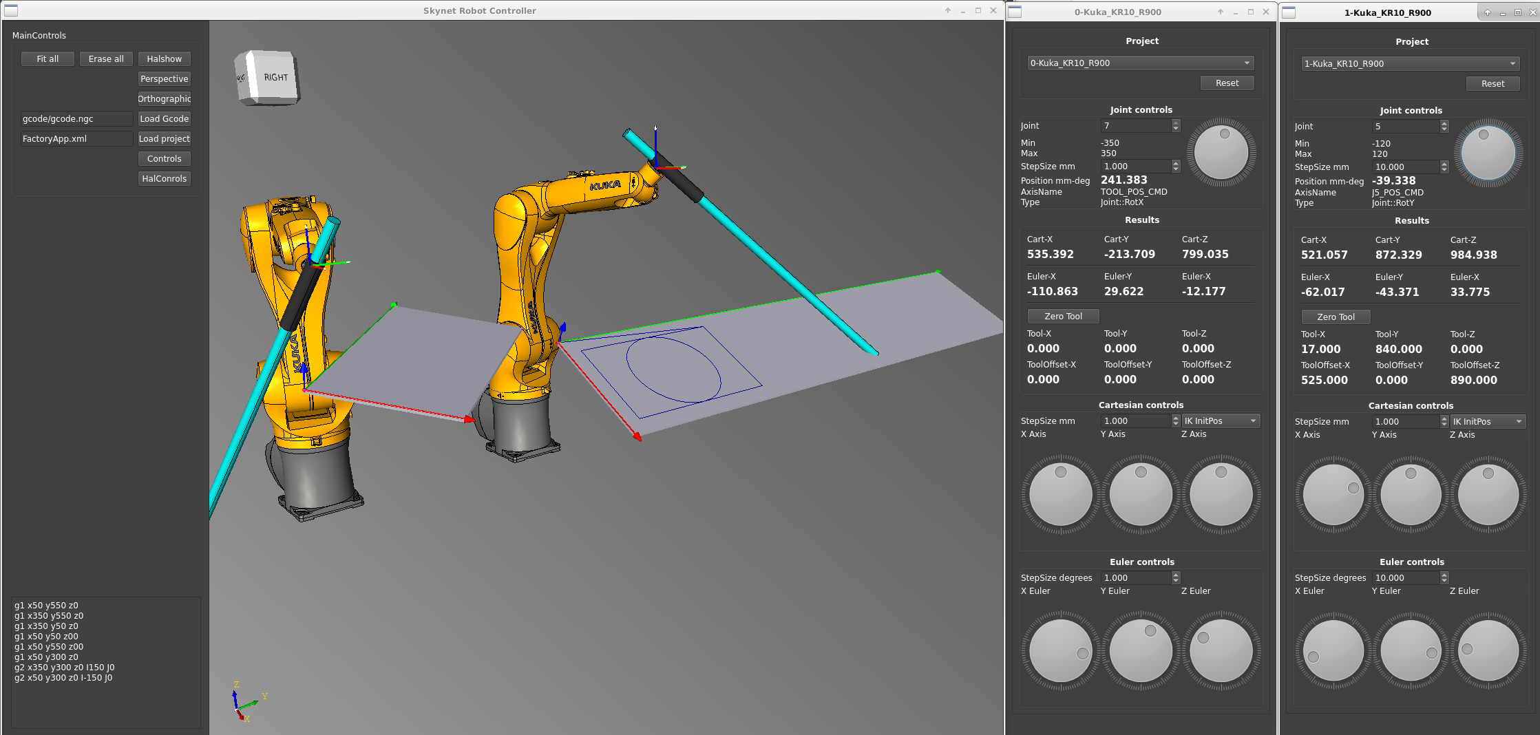
If you have a gcode file like this :
g1 x50 y550 z0
g1 x350 y550 z0
g1 x350 y50 z0
g1 x50 y50 z00
g1 x50 y550 z00
g1 x50 y300 z0
g2 x350 y300 z0 I150 J0
g2 x50 y300 z0 I-150 J0
And in your xml config file you have the Workframes defined as :
Then you select wich workframe you wanna use. And walla your gcode is applied to the WorkFrame.
Result so far.
It took quite a few hours to make the workframe basis including :
A box displaying the workframe sizes.
A green, red and blue tube + cone. (axis arrows)
A purple sphere. (origin)
Then i had to do some matrix transformating, rotation magic. And walla.
Please Log in or Create an account to join the conversation.
- Aciera
-

- Offline
- Administrator
-

- Posts: 4621
- Thank you received: 2045
Attachments:
Please Log in or Create an account to join the conversation.
- LinuxCNC
- General LinuxCNC Questions
- How would you design a real time application for cnc control in c / c++ ???


