- LinuxCNC
- General LinuxCNC Questions
- How would you design a real time application for cnc control in c / c++ ???
How would you design a real time application for cnc control in c / c++ ???
- Grotius
-
 Topic Author
- Offline
- Platinum Member
-

Less
More
- Posts: 2419
- Thank you received: 2348
04 Dec 2020 10:11 - 04 Dec 2020 12:34 #191018
by Grotius
Replied by Grotius on topic How would you design a real time application for cnc control in c / c++ ???
Hi,
A little update.
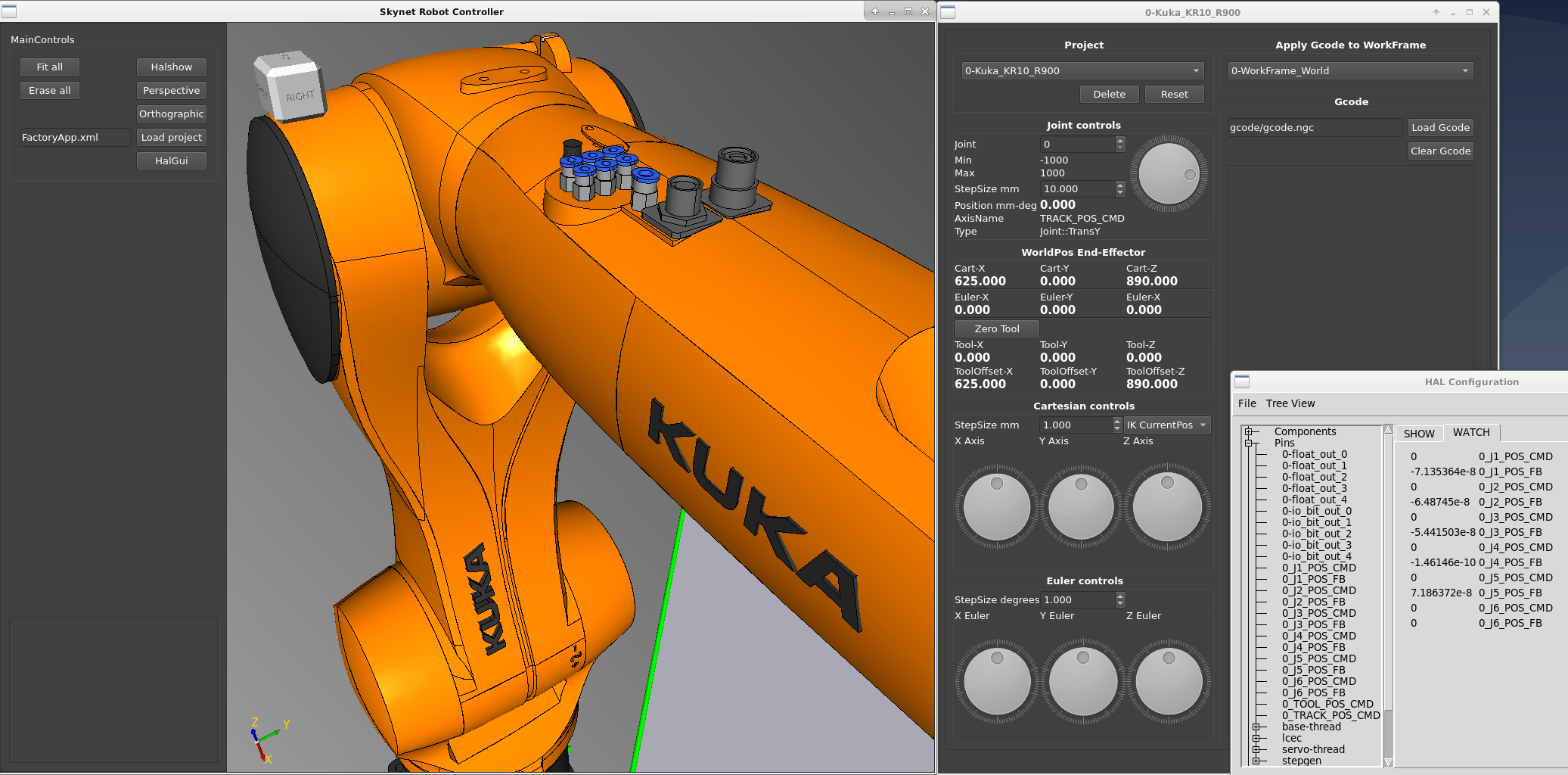
After i did making the iso. Finally the stepcolors are detailed. This is nice !
To save pc memory it now only load's the stepfile surfaces.
To get a more realistic machine movement,
I just experimented with updating the screen preview based on the "Position Feedback Value's"
from the Hal stepgenerator. My motors are connected and the output is nice.
Video that show's updating the machine movements on feedback position.
video
This is a example halfile used by above video.
I am thinking to integrate a stand alone motion planner now. This can be a hard job to do.
@Arciera,
This looks like what's also used by MoveIt! in the ROS framework. Not quite sure as it's been a while.
Yes.
Have you walked trough the source code already? Is it hard to understand for you? Or do you think something else?
Please let me know so i can improve it.
A video of the steppermotors running.
A little update.
After i did making the iso. Finally the stepcolors are detailed. This is nice !
To save pc memory it now only load's the stepfile surfaces.
To get a more realistic machine movement,
I just experimented with updating the screen preview based on the "Position Feedback Value's"
from the Hal stepgenerator. My motors are connected and the output is nice.
Video that show's updating the machine movements on feedback position.
video
This is a example halfile used by above video.
Warning: Spoiler!
# Terminal command to load this file.
#
# halcmd \-f ethercat.hal
# halcmd start
#
# halrun -U #stop

# If lcnc is master, we don't need to load threats :
loadrt threads name1=base-thread fp1=0 period1=15000 name2=servo-thread period2=1000000


loadusr -W /usr/share/ethercat/linuxcnc_ethercat/src/lcec_conf /home/user/Desktop/build-Skynet-Desktop-Debug/hal/ethercat-conf.xml
loadrt lcec

net ec-slaves-responding <= lcec.slaves-responding
net ec-link-up <= lcec.link-up
net ec-all-op <= lcec.all-op

addf lcec.read-all base-thread
addf lcec.write-all base-thread

# For example expand to : step_type=0,0,0,0,0,0 #for a 6 axis stepper robot.
loadrt stepgen step_type=0,0,0,0,0,0
addf stepgen.make-pulses base-thread

addf stepgen.capture-position servo-thread
addf stepgen.update-freq servo-thread


# Robot stepgeneratos parameters.

setp stepgen.0.position-scale 1300
setp stepgen.0.steplen 5
setp stepgen.0.stepspace 5
setp stepgen.0.dirhold 35000
setp stepgen.0.dirsetup 35000
setp stepgen.0.maxaccel 10
setp stepgen.0.maxvel 500
setp stepgen.0.enable 1

setp stepgen.1.position-scale 1300
setp stepgen.1.steplen 5
setp stepgen.1.stepspace 5
setp stepgen.1.dirhold 35000
setp stepgen.1.dirsetup 35000
setp stepgen.1.maxaccel 10
setp stepgen.1.maxvel 500
setp stepgen.1.enable 1

setp stepgen.2.position-scale 1300
setp stepgen.2.steplen 5
setp stepgen.2.stepspace 5
setp stepgen.2.dirhold 35000
setp stepgen.2.dirsetup 35000
setp stepgen.2.maxaccel 10
setp stepgen.2.maxvel 500
setp stepgen.2.enable 1

setp stepgen.3.position-scale 1300
setp stepgen.3.steplen 5
setp stepgen.3.stepspace 5
setp stepgen.3.dirhold 35000
setp stepgen.3.dirsetup 35000
setp stepgen.3.maxaccel 10
setp stepgen.3.maxvel 500
setp stepgen.3.enable 1

setp stepgen.4.position-scale 1300
setp stepgen.4.steplen 5
setp stepgen.4.stepspace 5
setp stepgen.4.dirhold 35000
setp stepgen.4.dirsetup 35000
setp stepgen.4.maxaccel 10
setp stepgen.4.maxvel 500
setp stepgen.4.enable 1

setp stepgen.5.position-scale 1300
setp stepgen.5.steplen 5
setp stepgen.5.stepspace 5
setp stepgen.5.dirhold 35000
setp stepgen.5.dirsetup 35000
setp stepgen.5.maxaccel 10
setp stepgen.5.maxvel 500
setp stepgen.5.enable 1

# Connecting robot joints J2 and J3.

#EL2124 4x 5us pulse
net J2_step => stepgen.0.step 	lcec.0.output_stepper_1.dout-0
net J2_dir 	=> stepgen.0.dir 	lcec.0.output_stepper_1.dout-1
net J3_step => stepgen.1.step 	lcec.0.output_stepper_1.dout-2
net J3_dir  => stepgen.1.dir 	lcec.0.output_stepper_1.dout-3

#EL2124 4x 5us pulse
#net J4_step => stepgen.2.step 	lcec.0.output_stepper_2.dout-0
#net J4_dir  => stepgen.2.dir 	lcec.0.output_stepper_2.dout-1
#net J5_step => stepgen.3.step 	lcec.0.output_stepper_2.dout-2
#net J5_dir  => stepgen.3.dir 	lcec.0.output_stepper_2.dout-3

# Connecting gui float value "J2_POS_CMD" to stepgenerator

net NETJ1 => 0_J1_POS_CMD stepgen.0.position-cmd
net NETJ2 => 0_J2_POS_CMD stepgen.1.position-cmd
net NETJ3 => 0_J3_POS_CMD stepgen.2.position-cmd
net NETJ4 => 0_J4_POS_CMD stepgen.3.position-cmd
net NETJ5 => 0_J5_POS_CMD stepgen.4.position-cmd
net NETJ6 => 0_J6_POS_CMD stepgen.5.position-cmd

# Connecting stepgenerator position feedback to update opencascade robot.

net OCEJ1 => 0_J1_POS_FB stepgen.0.position-fb
net OCEJ2 => 0_J2_POS_FB stepgen.1.position-fb
net OCEJ3 => 0_J3_POS_FB stepgen.2.position-fb
net OCEJ4 => 0_J4_POS_FB stepgen.3.position-fb
net OCEJ5 => 0_J5_POS_FB stepgen.4.position-fb
net OCEJ6 => 0_J6_POS_FB stepgen.5.position-fb

#net bitdata bitpin lcec.0.output_stepper_2.dout-2
I am thinking to integrate a stand alone motion planner now. This can be a hard job to do.
@Arciera,
This looks like what's also used by MoveIt! in the ROS framework. Not quite sure as it's been a while.
Yes.
Have you walked trough the source code already? Is it hard to understand for you? Or do you think something else?
Please let me know so i can improve it.
A video of the steppermotors running.
Attachments:
Last edit: 04 Dec 2020 12:34 by Grotius.
The following user(s) said Thank You: tommylight
Please Log in or Create an account to join the conversation.
- Aciera
-

- Offline
- Administrator
-

Less
More
- Posts: 4718
- Thank you received: 2114
04 Dec 2020 15:19 - 04 Dec 2020 15:23 #191035
by Aciera
Thanks for the video.
Is that still going through LinuxCNC or are the motors handled by your code?
Replied by Aciera on topic How would you design a real time application for cnc control in c / c++ ???
I haven't done much, as I'm trying to reverse engineer my robots teach in pendant to see if I could some how use that together with linuxCNC.Have you walked trough the source code already? Is it hard to understand for you? Or do you think something else?
Thanks for the video.
Is that still going through LinuxCNC or are the motors handled by your code?
Last edit: 04 Dec 2020 15:23 by Aciera.
Please Log in or Create an account to join the conversation.
- Grotius
-
Topic Author
- Offline
- Platinum Member
-
Less
More
- Posts: 2419
- Thank you received: 2348
14 Dec 2020 23:57 - 15 Dec 2020 00:08 #191999
by Grotius
Replied by Grotius on topic How would you design a real time application for cnc control in c / c++ ???
Hi Arciera,
The motors are handled by trough hal.
I haven't done much, as I'm trying to reverse engineer my robots teach in pendant to see if I could some how use that together with linuxCNC.
Interesting !
I had some problems to solve. The Qt program was not able to rotate the motors trough my wishes. It was doing a quite good
job. But i was not satisfied ! The solution is to bring the Ik and Fk outside of the QT app as stand alone c++ component.
In the meantime i made a linuxcnc kinematics component for Ik and Fk based on KDL kinematics.
The problem in this case is that realtime code is in C and the KDL library is in C++. So downgrading KDL to c is an option.
But that would be silly to do.
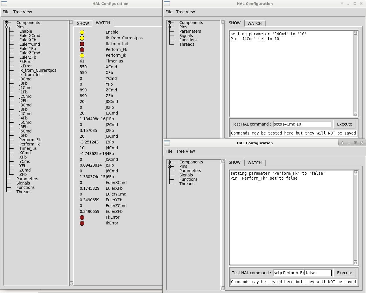
So i made a tiny C++ program that act's as a realtime component. The output is very promising. When performing IK and FK the
cyclus time is < 100 us. In the QT program the position command update time was 10 times a second. So a very big improvement.
So if the Stepgen was updated 10 times a second you will hear the motors change speed 10 times a second. If the update is for example 1000 times a second, you will hear a perfect motor speed increase and decrease sound.
You could use this code too. The code is written as basic as possible to be more readable for users.
Later on adding the xml config file input etc. is easy to do. For now the kdl chain setup is written in the code.
Users can choose to do "Perform_IK" or "Perform_FK"
You see the chrono timer is doing a cycle of 61 nanoseconds. This is really fast.
I will add a sort of synchronisation pin to stay in line with the servo-threat and avoid making waste calculations.
SourceCode
The motors are handled by trough hal.
I haven't done much, as I'm trying to reverse engineer my robots teach in pendant to see if I could some how use that together with linuxCNC.
Interesting !
I had some problems to solve. The Qt program was not able to rotate the motors trough my wishes. It was doing a quite good
job. But i was not satisfied ! The solution is to bring the Ik and Fk outside of the QT app as stand alone c++ component.
In the meantime i made a linuxcnc kinematics component for Ik and Fk based on KDL kinematics.
The problem in this case is that realtime code is in C and the KDL library is in C++. So downgrading KDL to c is an option.
But that would be silly to do.
So i made a tiny C++ program that act's as a realtime component. The output is very promising. When performing IK and FK the
cyclus time is < 100 us. In the QT program the position command update time was 10 times a second. So a very big improvement.
So if the Stepgen was updated 10 times a second you will hear the motors change speed 10 times a second. If the update is for example 1000 times a second, you will hear a perfect motor speed increase and decrease sound.
You could use this code too. The code is written as basic as possible to be more readable for users.
Later on adding the xml config file input etc. is easy to do. For now the kdl chain setup is written in the code.
Users can choose to do "Perform_IK" or "Perform_FK"
You see the chrono timer is doing a cycle of 61 nanoseconds. This is really fast.
I will add a sort of synchronisation pin to stay in line with the servo-threat and avoid making waste calculations.
SourceCode
Attachments:
Last edit: 15 Dec 2020 00:08 by Grotius.
The following user(s) said Thank You: tommylight, Aciera
Please Log in or Create an account to join the conversation.
- Grotius
-
Topic Author
- Offline
- Platinum Member
-
Less
More
- Posts: 2419
- Thank you received: 2348
17 Dec 2020 07:40 - 17 Dec 2020 07:42 #192232
by Grotius
Replied by Grotius on topic How would you design a real time application for cnc control in c / c++ ???
Hi,
I succeeded to implement a tiny test motion planner that run's trough 3 points. The result is a smooth motor acceleration, deacceleration.
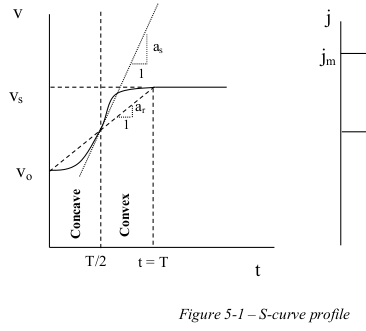
This test motion planner has a lineair acceleration curve. So i am not satisfied with this type and have written a
S curve acceleration / deacceleration type.
The source for the S-curve is at my github channel
No i have to put everything together in new motion planner. This will be a c++ hal component motion planner.
So far so good, have a nice day !
I succeeded to implement a tiny test motion planner that run's trough 3 points. The result is a smooth motor acceleration, deacceleration.
This test motion planner has a lineair acceleration curve. So i am not satisfied with this type and have written a
S curve acceleration / deacceleration type.
The source for the S-curve is at my github channel
No i have to put everything together in new motion planner. This will be a c++ hal component motion planner.
So far so good, have a nice day !
Last edit: 17 Dec 2020 07:42 by Grotius.
The following user(s) said Thank You: Aciera
Please Log in or Create an account to join the conversation.
- rodw
-

- Offline
- Platinum Member
-
Less
More
- Posts: 11963
- Thank you received: 4075
17 Dec 2020 09:48 #192236
by rodw
Replied by rodw on topic How would you design a real time application for cnc control in c / c++ ???
There may be another way. If you have a look at /src/emc/tp/tp.c
there is this code starting at line 2276
Ref: github.com/LinuxCNC/linuxcnc/blob/master/src/emc/tp/tp.c
So it might be possible to intercept this and apply a positive or negative offset to position and velocity for each time step (servo thread cycle) There are some hard bits for spindle synchronised motion but that is probably not necessary for a robot or a plasma cutter.
Good luck. Keep us updated!
there is this code starting at line 2276
/**
 * Compute updated position and velocity for a timestep based on a trapezoidal
 * motion profile.
 * @param tc trajectory segment being processed.
 *
 * Creates the trapezoidal velocity profile based on the segment's velocity and
 * acceleration limits. The formula has been tweaked slightly to allow a
 * non-zero velocity at the instant the target is reached.
 */
void tpCalculateTrapezoidalAccel(TP_STRUCT const * const tp, TC_STRUCT * const tc, TC_STRUCT const * const nexttc,
        double * const acc, double * const vel_desired)
Ref: github.com/LinuxCNC/linuxcnc/blob/master/src/emc/tp/tp.c
So it might be possible to intercept this and apply a positive or negative offset to position and velocity for each time step (servo thread cycle) There are some hard bits for spindle synchronised motion but that is probably not necessary for a robot or a plasma cutter.
Good luck. Keep us updated!
Please Log in or Create an account to join the conversation.
- Grotius
-
Topic Author
- Offline
- Platinum Member
-
Less
More
- Posts: 2419
- Thank you received: 2348
17 Dec 2020 14:20 - 17 Dec 2020 14:21 #192248
by Grotius
Replied by Grotius on topic How would you design a real time application for cnc control in c / c++ ???
Hi Rodw,
The code you have found for me it not usable for me at this moment. Thanks for the suggestion !
The idea of a velocity e.offset is quite nice. But i will try it to code with the S-curve. It will take some time.
The way i am planning to use the S-curve is to freely assign it to a motion at the left or right side or at no side. This is
all calculated with look ahead logic in mind.
I found nice music, helps with coding.
اهنگ عالییه ایران رفتم غذاهاتون خیلی خوش مزه بود . مردم ایران خیلی خوبه
Last edit: 17 Dec 2020 14:21 by Grotius.
Please Log in or Create an account to join the conversation.
- grijalvap
-

- Offline
- Elite Member
-

Less
More
- Posts: 200
- Thank you received: 63
18 Dec 2020 00:51 #192289
by grijalvap
Replied by grijalvap on topic How would you design a real time application for cnc control in c / c++ ???
I Think what rodw is traying to indicate is that you can replace the void tpCalculateTrapezoidalAccel funtion with the one you write in order to test and implement.
The following user(s) said Thank You: rodw, Grotius
Please Log in or Create an account to join the conversation.
- rodw
-
- Offline
- Platinum Member
-
Less
More
- Posts: 11963
- Thank you received: 4075
18 Dec 2020 01:55 #192295
by rodw
Yes almost, I think at that point, the motion controller already knows the start and end points of the acceleration segment and that procedure is calculating ( planning) where it needs to be right now (eg on that servo thread cycle). So if you thought of your S curve as being an offset either above or below the trapezoidal path at any given time (eg below on the concave start and above at the convex end), you could let that procedure calculate its normal trapezoidal settings, then apply the S curve offset for position and acceleration at that point.
You would need to consider how to handle the violation of acceleration limits that will occur in the transition from concave to convex, but surely, that is a matter of tuning. I suspect you could calculate the maximum acceleration required to arrive the S curve end point on time and allow for that by reducing the trapezoidal acceleration settings the motion planner is using from the ini file settings
I have not looked in detail at tp.c but that is the code where it all happens!
Replied by rodw on topic How would you design a real time application for cnc control in c / c++ ???
I Think what rodw is traying to indicate is that you can replace the void tpCalculateTrapezoidalAccel function with the one you write in order to test and implement.
Yes almost, I think at that point, the motion controller already knows the start and end points of the acceleration segment and that procedure is calculating ( planning) where it needs to be right now (eg on that servo thread cycle). So if you thought of your S curve as being an offset either above or below the trapezoidal path at any given time (eg below on the concave start and above at the convex end), you could let that procedure calculate its normal trapezoidal settings, then apply the S curve offset for position and acceleration at that point.
You would need to consider how to handle the violation of acceleration limits that will occur in the transition from concave to convex, but surely, that is a matter of tuning. I suspect you could calculate the maximum acceleration required to arrive the S curve end point on time and allow for that by reducing the trapezoidal acceleration settings the motion planner is using from the ini file settings
I have not looked in detail at tp.c but that is the code where it all happens!
The following user(s) said Thank You: Grotius
Please Log in or Create an account to join the conversation.
- Aciera
-
- Offline
- Administrator
-
Less
More
- Posts: 4718
- Thank you received: 2114
18 Dec 2020 17:19 #192353
by Aciera
Replied by Aciera on topic How would you design a real time application for cnc control in c / c++ ???
@Grotius
So, thanks to dm17ry, I finally have everything on the same machine. Switchkins, the Mitsubishi driver and your ISO with qt creator and your Skynet compiling.
Next step will be to make the model of my RV-6SDL robot and try to get the joint positions from linuxcnc into the skynet app.
I'm sure I'll be back with questions.
The following user(s) said Thank You: Grotius
Please Log in or Create an account to join the conversation.
- Grotius
-
Topic Author
- Offline
- Platinum Member
-
Less
More
- Posts: 2419
- Thank you received: 2348
18 Dec 2020 18:57 - 18 Dec 2020 19:16 #192364
by Grotius
Replied by Grotius on topic How would you design a real time application for cnc control in c / c++ ???
@Grijalvap,
I Think what rodw is traying to indicate is that you can replace the void tpCalculateTrapezoidalAccel funtion with the one you write in order to test and implement.
Ahh. I didn't mention that.
If you ask me. I am not a fan of some parts of the lcnc source code trough the complexity and or missing comments.
That's why i write custom code that will work with hal as rt engine.
Attached code works, but try to integrate such a code.. I think integrating the code is a more complex task then actual writing the
S-curve code.
@Rodw,
Yes almost, I think at that point, the motion controller already knows the start and end points of the acceleration segment and that procedure is calculating ( planning) where it needs to be right now (eg on that servo thread cycle). So if you thought of your S curve as being an offset either above or below the trapezoidal path at any given time (eg below on the concave start and above at the convex end), you could let that procedure calculate its normal trapezoidal settings, then apply the S curve offset for position and acceleration at that point.
I'am not sure if that will work, have to think about that.
If you can return the toolpoint, the acc and vel it will work.
I suspect you could calculate the maximum acceleration required to arrive the S curve
The max acceleration for the S-curve = 2* normal lineair acceleration. That max acceleration point is exact in the middle of the acc / dcc path, and is called "the inflection point".
@Arciera,
dm17ry
?? Hahaa.. What do you mean with this?
Next step will be to make the model of my RV-6SDL robot and try to get the joint positions from linuxcnc into the skynet app.
Making the stepmodel is oke. Try to get it working in the skynet app. Take a Skynet release that fit's your needs.
For actual controlling the robot, maybe wait a few day's until i have a release that is capable to control your robot.
Oke i have written the S-curve code in C comp style, and did a graph plot with Qt to show what is happening.
- Cyan is concave period
- Blue is convex period
- Gray is at speed period
- Green is acceleration
- startpoint x0 y0 z0, endpoint x600 y200 z0
- MaxVel = 20 mm/sec
- Acceleration = 1 mm/sec^2
- Output graph :
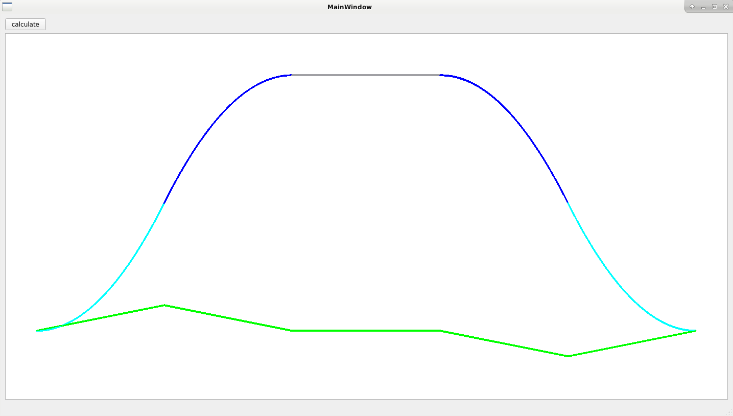
From S-curve document : doc
Ok. This looks oke to me.
Now i can try to expand the s-curve code to work with motioncommands.
QT source code with graph view : SourceCode
I Think what rodw is traying to indicate is that you can replace the void tpCalculateTrapezoidalAccel funtion with the one you write in order to test and implement.
Ahh. I didn't mention that.
If you ask me. I am not a fan of some parts of the lcnc source code trough the complexity and or missing comments.
That's why i write custom code that will work with hal as rt engine.
Attached code works, but try to integrate such a code.. I think integrating the code is a more complex task then actual writing the
S-curve code.
@Rodw,
Yes almost, I think at that point, the motion controller already knows the start and end points of the acceleration segment and that procedure is calculating ( planning) where it needs to be right now (eg on that servo thread cycle). So if you thought of your S curve as being an offset either above or below the trapezoidal path at any given time (eg below on the concave start and above at the convex end), you could let that procedure calculate its normal trapezoidal settings, then apply the S curve offset for position and acceleration at that point.
I'am not sure if that will work, have to think about that.
If you can return the toolpoint, the acc and vel it will work.
I suspect you could calculate the maximum acceleration required to arrive the S curve
The max acceleration for the S-curve = 2* normal lineair acceleration. That max acceleration point is exact in the middle of the acc / dcc path, and is called "the inflection point".
@Arciera,
dm17ry
?? Hahaa.. What do you mean with this?
Next step will be to make the model of my RV-6SDL robot and try to get the joint positions from linuxcnc into the skynet app.
Making the stepmodel is oke. Try to get it working in the skynet app. Take a Skynet release that fit's your needs.
For actual controlling the robot, maybe wait a few day's until i have a release that is capable to control your robot.
Oke i have written the S-curve code in C comp style, and did a graph plot with Qt to show what is happening.
- Cyan is concave period
- Blue is convex period
- Gray is at speed period
- Green is acceleration
- startpoint x0 y0 z0, endpoint x600 y200 z0
- MaxVel = 20 mm/sec
- Acceleration = 1 mm/sec^2
- Output graph :
From S-curve document : doc
Ok. This looks oke to me.
Now i can try to expand the s-curve code to work with motioncommands.
QT source code with graph view : SourceCode
Attachments:
Last edit: 18 Dec 2020 19:16 by Grotius.
Please Log in or Create an account to join the conversation.
- LinuxCNC
- General LinuxCNC Questions
- How would you design a real time application for cnc control in c / c++ ???
Time to create page: 0.333 seconds