hobbing helical gear
- timo
- Offline
- Elite Member
-

Less
More
- Posts: 203
- Thank you received: 60
24 Apr 2021 19:12 - 24 Apr 2021 19:18 #206963
by timo
Replied by timo on topic hobbing helical gear
Outcome of today.
Actually I am not sure if shifting the hob is the right expression.
Today I tried this again.
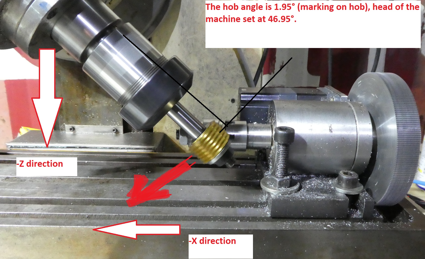
The wokhead is set to 46.95° ( marking on hob 1.95° plus 45° helix angle)
The number of teeth is entered into the invert.0.in on hal file.
Then the spindle rotation and gear blank rotation is in sync.
Now the workhead travels parallel to the tooth of the hob. So it moves left and down for a climb cut. Actually it is not really shifted, but only traversing. As you can see the oily mess is only on the lower part of the hob.
I made a horrible mess driving it down at a 45° angle, this was a bad Idea and wrong..., so one gearblank was scrap. It must travel along the pitch of the hob at its angle ( 46.19°)
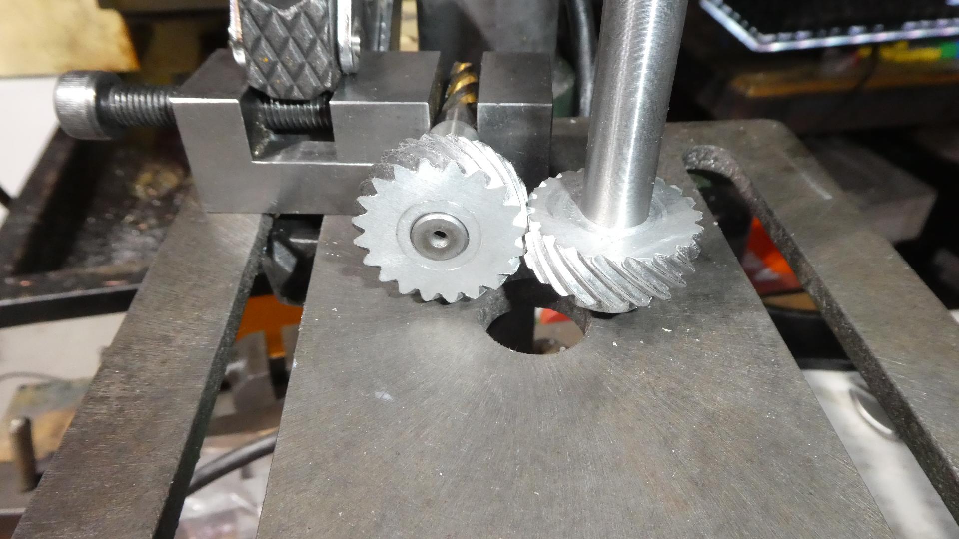
I cut two gears that way.
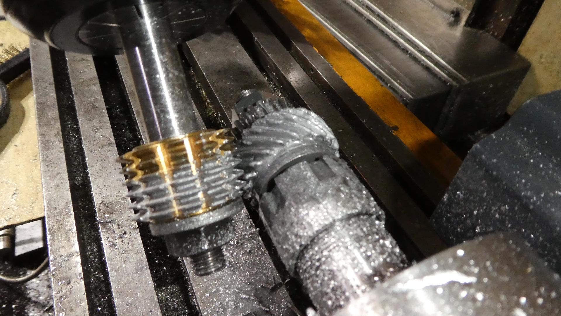
They mesh O.K. as far as I can tell.
Then I played around with the virtual differential gear.
Here is a short 30s clip to show the proof of concept.
You can see that the gear rotation speed is adjusted automatically based on the speed the gear has relative to the hob, I think that is what jefsaro was lookig for.
I made this video by tweaking the value roughly. The next step will be to create a proper formula to allow to put the correct value into the program.
Greetings Timo
p.s. in the video I am jogging the machine manually at different speeds. So if the value is set correct later multiple depth can be cut or the cutting feed speed could be adjusted during the cutting.
Actually I am not sure if shifting the hob is the right expression.
Today I tried this again.
The wokhead is set to 46.95° ( marking on hob 1.95° plus 45° helix angle)
The number of teeth is entered into the invert.0.in on hal file.
Then the spindle rotation and gear blank rotation is in sync.
Now the workhead travels parallel to the tooth of the hob. So it moves left and down for a climb cut. Actually it is not really shifted, but only traversing. As you can see the oily mess is only on the lower part of the hob.
I made a horrible mess driving it down at a 45° angle, this was a bad Idea and wrong..., so one gearblank was scrap. It must travel along the pitch of the hob at its angle ( 46.19°)
I cut two gears that way.
They mesh O.K. as far as I can tell.
Then I played around with the virtual differential gear.
Here is a short 30s clip to show the proof of concept.
You can see that the gear rotation speed is adjusted automatically based on the speed the gear has relative to the hob, I think that is what jefsaro was lookig for.
I made this video by tweaking the value roughly. The next step will be to create a proper formula to allow to put the correct value into the program.
Greetings Timo
p.s. in the video I am jogging the machine manually at different speeds. So if the value is set correct later multiple depth can be cut or the cutting feed speed could be adjusted during the cutting.
Attachments:
Last edit: 24 Apr 2021 19:18 by timo. Reason: p.s.
The following user(s) said Thank You: Aciera
Please Log in or Create an account to join the conversation.
- J Green
- Offline
- Elite Member
-
Less
More
- Posts: 164
- Thank you received: 24
25 Apr 2021 02:02 #206988
by J Green
Replied by J Green on topic hobbing helical gear
jefsaro an others
It is neat seeing what is being done for making gears by using a hob . But for those living in a hob-less world would what MuellerNick shows be useful ?
Also, Wilfried Smekens SA-CNC-Club AKA = You-Tube skidloaders1 shows gear cutting with slitting saw on 4 axis mill and even includes his program in the "Show More " section .
Hope this is of some use an would be interested in your thoughts --
Bob
The following user(s) said Thank You: Aciera
Please Log in or Create an account to join the conversation.
- timo
- Offline
- Elite Member
-
Less
More
- Posts: 203
- Thank you received: 60
25 Apr 2021 04:59 #206992
by timo
Replied by timo on topic hobbing helical gear
For my part the method of mueller nick will possibly not work. I fear my rotary axis has not enough torque and too much backlash. It is on the endless list of improvements.
We are not living in a hobless world, but in a world with lots of alternatives for almost everything. Lots of ways to do it. And it seems they are not getting less.
Timo
We are not living in a hobless world, but in a world with lots of alternatives for almost everything. Lots of ways to do it. And it seems they are not getting less.
Timo
Please Log in or Create an account to join the conversation.
- Henk
- Offline
- Platinum Member
-

Less
More
- Posts: 408
- Thank you received: 92
03 May 2021 09:28 #207712
by Henk
Replied by Henk on topic hobbing helical gear
HI
For a while now i thought about using external offsets to do gear hobbing. Preliminary testing indicates that it should be ok to do it that way.
My plan is to do an actual test on some nylon or wood or something soft shortly, but i am attaching parts of my config for comments
I wrote a component that calculates the external offset counts and scale from simple gear and tool data. The component also controls the axis.L.eoffset-enable pin to prevent unexpected motion when the gear/tool data is changed.
Some known issues that needs some attention in my config....
1. Spindle acceleration is too fast, i plan to use a limit3 component to limit the spindle ramp up. Spindle max speed can also be limited, gear hobbing is normally done at relatively slow speeds
2. Rotary axis tuning - I need to get faster acceleration, or limit the linear axis acceleration so that the rotary axis can keep up.
Hal file ...
Pyvcp panel...
For a while now i thought about using external offsets to do gear hobbing. Preliminary testing indicates that it should be ok to do it that way.
My plan is to do an actual test on some nylon or wood or something soft shortly, but i am attaching parts of my config for comments
I wrote a component that calculates the external offset counts and scale from simple gear and tool data. The component also controls the axis.L.eoffset-enable pin to prevent unexpected motion when the gear/tool data is changed.
Some known issues that needs some attention in my config....
1. Spindle acceleration is too fast, i plan to use a limit3 component to limit the spindle ramp up. Spindle max speed can also be limited, gear hobbing is normally done at relatively slow speeds
2. Rotary axis tuning - I need to get faster acceleration, or limit the linear axis acceleration so that the rotary axis can keep up.
Hal file ...
loadrt gearhob
addf gearhob servo-thread

#----external offset----


net eoffs-counts <= gearhob.eoffset-counts =>  axis.a.eoffset-counts
net eoffs-scale <= gearhob.eoffset-scale => axis.a.eoffset-scale

#-----gearhob component-----
setp gearhob.spindle-scale [SPINDLE_9]ENCODER_SCALE
setp gearhob.axial-scale [JOINT_0]ENCODER_SCALE
setp gearhob.tangential-scale [JOINT_2]ENCODER_SCALE
setp gearhob.rot-axis-counts 360000

net x-axis-count <= hm2_5i25.0.encoder.00.count => gearhob.axial-axis-counts
net z-axis-count <= hm2_5i25.0.encoder.02.count => gearhob.tangential-axis-counts
net spindle-count <= hm2_5i25.0.encoder.04.count => gearhob.spindle-counts

net num_teeth <= pyvcp.no-teeth => gearhob.zj
net hob-starts <= pyvcp.hob-starts => gearhob.zh
net lead <= pyvcp.lead => gearhob.lead
net ref-dia <= pyvcp.ref-dia => gearhob.ref-dia
net enable-eoffset <= gearhob.enable-out => axis.a.eoffset-enable => pyvcp.is-enabled
net enable-button <= pyvcp.enable => gearhob.enable-in
net disable-button <= pyvcp.disable => gearhob.disable-in
Pyvcp panel...
<?xml version="1.0" encoding="UTF-8"?>

-<pyvcp>


-<vbox>

<relief>RIDGE</relief>


-<label>

<text>"Hobbing:"</text>

</label>


-<hbox>


-<label>

<text>"Z = "</text>

<font>("Helvetica",8)</font>

</label>


-<spinbox>

<halpin>"no-teeth"</halpin>

<min_>10</min_>

<max_>400</max_>

<initval>25</initval>

<resolution>1</resolution>

<format>("2.0f")</format>

<font>("Helvetica",8)</font>

</spinbox>

</hbox>


-<hbox>


-<label>

<text>"HOB Z = "</text>

<font>("Helvetica",8)</font>

</label>


-<spinbox>

<halpin>"hob-starts"</halpin>

<min_>-8</min_>

<max_>8</max_>

<initval>1</initval>

<resolution>1</resolution>

<format>("2.0f")</format>

<font>("Helvetica",8)</font>

</spinbox>

</hbox>


-<hbox>


-<label>

<text>"Lead = "</text>

<font>("Helvetica",8)</font>

</label>


-<spinbox>

<halpin>"lead"</halpin>

<min_>-99999999</min_>

<max_>99999999</max_>

<initval>99999999</initval>

<resolution>1</resolution>

<format>("8.3f")</format>

<font>("Helvetica",8)</font>

</spinbox>

</hbox>


-<hbox>


-<label>

<text>"Ref Dia = "</text>

<font>("Helvetica",8)</font>

</label>


-<spinbox>

<halpin>"ref-dia"</halpin>

<min_>0</min_>

<max_>200</max_>

<initval>50</initval>

<resolution>1</resolution>

<format>("3.4f")</format>

<font>("Helvetica",8)</font>

</spinbox>

</hbox>


-<hbox>


-<button>

<relief>RAISED</relief>

<halpin>"enable"</halpin>

<text>"Enable"</text>

<font>("Helvetica",7)</font>

<bd>3</bd>

</button>


-<button>

<relief>RAISED</relief>

<halpin>"disable"</halpin>

<text>"Disable"</text>

<font>("Helvetica",7)</font>

<bd>3</bd>

</button>

</hbox>


-<hbox>


-<label>

<text>"Is Enabled"</text>

<font>("Helvetica",8)</font>

</label>


-<led>

<halpin>"is-enabled"</halpin>

<size>15</size>

<on_color>"green"</on_color>

<off_color>"red"</off_color>

</led>

</hbox>

</vbox>

<!-- Include your PyVCP panel here. The contents of this file will not be overwritten when you run stepconf again. -->


</pyvcp>
Attachments:
Please Log in or Create an account to join the conversation.
- timo
- Offline
- Elite Member
-
Less
More
- Posts: 203
- Thank you received: 60
03 May 2021 12:49 - 03 May 2021 12:59 #207720
by timo
Replied by timo on topic hobbing helical gear
Hello Henk,
I did not yet understand all you posted.
Accelleration Problems I had too sometimes. I just "fixed" that in the frequency inverter for the Spindle. (slowlyslowly ramping up, maximum speed of the machine is now 600 rpm with a much smaller motor and 1:5 gearbox ). The bigger motor was better for milling, but had no torque at lower speeds.
For the gear blank rotaty axis I just switch the spindle on and then wait until the spindle runs for a minute or so. "ugly fix, but the stepper on the rotary axis just cannot keep up at certains speeds"
The hal file I more or less, bluntly copied from Andy Pugh")
There is one scale that connects the gear blank axis to the x axis
( they are prallel on my machine). I adjusted everything so that if the value of axis.1.scale is 1 it will rotate the gear blank a full circle for every mm moved by the x axis.
Then for a metric gear. The value for axis.1.scale is
axis.1.scale = tan(gear_angle) / (Pi()*number_of_tooth*module)/cos(gear_angle)) = tan(gear_angle) / Pi()*pcd
At the moment I just calculated that with a calculator and feed it into the hal configuration manually.
That means the axis.1.scale changes for every gear blank based on module, number of teeth and helix angle.
Then the gear blank rotates according to the x axis travel and the downward motion -z of the hob ( see my earlier picture) is not required anymore and the hob travels only prallel to the gear blank axis.
I tried this since last post by first cutting a set of gears based on the sketch from previous post. Then driving hob and gear based on the new method.
Now next step would be a proper hob shifting based on z-axis travel to wear the hob evenly.
Greetings Timo
I did not yet understand all you posted.
Accelleration Problems I had too sometimes. I just "fixed" that in the frequency inverter for the Spindle. (slowlyslowly ramping up, maximum speed of the machine is now 600 rpm with a much smaller motor and 1:5 gearbox ). The bigger motor was better for milling, but had no torque at lower speeds.
For the gear blank rotaty axis I just switch the spindle on and then wait until the spindle runs for a minute or so. "ugly fix, but the stepper on the rotary axis just cannot keep up at certains speeds"
The hal file I more or less, bluntly copied from Andy Pugh
There is one scale that connects the gear blank axis to the x axis
( they are prallel on my machine). I adjusted everything so that if the value of axis.1.scale is 1 it will rotate the gear blank a full circle for every mm moved by the x axis.
Then for a metric gear. The value for axis.1.scale is
axis.1.scale = tan(gear_angle) / (Pi()*number_of_tooth*module)/cos(gear_angle)) = tan(gear_angle) / Pi()*pcd
At the moment I just calculated that with a calculator and feed it into the hal configuration manually.
That means the axis.1.scale changes for every gear blank based on module, number of teeth and helix angle.
Then the gear blank rotates according to the x axis travel and the downward motion -z of the hob ( see my earlier picture) is not required anymore and the hob travels only prallel to the gear blank axis.
I tried this since last post by first cutting a set of gears based on the sketch from previous post. Then driving hob and gear based on the new method.
Now next step would be a proper hob shifting based on z-axis travel to wear the hob evenly.
Greetings Timo
Last edit: 03 May 2021 12:59 by timo. Reason: reason for hob shifting added.
Please Log in or Create an account to join the conversation.
- andypugh
-

- Offline
- Moderator
-

Less
More
- Posts: 19886
- Thank you received: 4645
03 May 2021 22:50 - 03 May 2021 22:51 #207759
by andypugh
Replied by andypugh on topic hobbing helical gear
I have my config set up so that LinuxCNC is largely unaware of the hobbing rotation. The A-axis position is added on to the hobbing-position in HAL.
Initially I didn't even have an A axis that LinuxCNC was aware of, but I decided it was handy to be able to jog the A axis to adjust the angular phase (and to tighten the camlocks on the chuck)
Here is the hobbing.comp that I use, it really isn't very complex.
Initially I didn't even have an A axis that LinuxCNC was aware of, but I decided it was handy to be able to jog the A axis to adjust the angular phase (and to tighten the camlocks on the chuck)
Here is the hobbing.comp that I use, it really isn't very complex.
component hobbing "synchronise a rotary axis to the spindle";

pin in float teeth;
pin in float starts = 1;
pin in float spindle-pos;
pin in float spindle-vel;
pin in float A-pos-cmd;
pin in float gear-pos-fb;

pin out float gear-pos;
pin out float gear-vel;
pin out float A-pos-fb;

author "andypugh";
license "GPL v2+";

function _;

;;

FUNCTION(_){
    static double pos_ref;
    static double spindle_ref;
    static int old_teeth;

    if (old_teeth != teeth){
        pos_ref = gear_pos_fb;
        spindle_ref = spindle_pos;
        old_teeth = teeth;
    }
    if (teeth != 0) {
        gear_pos = pos_ref + 360*starts*(spindle_pos - spindle_ref)/teeth + A_pos_cmd;
        gear_vel = spindle_vel / teeth;
        A_pos_fb = gear_pos_fb - pos_ref - 360*starts*(spindle_pos - spindle_ref)/teeth;
    } else {
        gear_pos = pos_ref + A_pos_cmd;
        gear_vel = 0;
        A_pos_fb = gear_pos_fb - pos_ref;
    }
}
Last edit: 03 May 2021 22:51 by andypugh.
Please Log in or Create an account to join the conversation.
- yrsiddhapura
- Offline
- Premium Member
-

Less
More
- Posts: 134
- Thank you received: 5
04 Aug 2021 12:07 #216902
by yrsiddhapura
Replied by yrsiddhapura on topic hobbing helical gear
Hello LCNC Community
@Henk
Does your pfauter p500 could cut helical gear ?
@Andypugh
For maths of Differential Indexing of helical gear it could help
I also want to convert mine manual Hobing machine with Linuxcnc
@Henk
Does your pfauter p500 could cut helical gear ?
@Andypugh
For maths of Differential Indexing of helical gear it could help
I also want to convert mine manual Hobing machine with Linuxcnc
Please Log in or Create an account to join the conversation.
- ContinenteCNC
-

- Offline
- Premium Member
-
Less
More
- Posts: 97
- Thank you received: 44
07 Aug 2021 00:42 - 07 Aug 2021 00:48 #217093
by ContinenteCNC
Replied by ContinenteCNC on topic hobbing helical gear
I’ve been planning to take some time to dive into helical hobbing for a long time. I struggle to make sense with the geometry in my head. I can’t seem to visualize what makes straight teeth hobbing different from helical ones.
Then I found this video. This guy simple uses the very same electronic gearing for both, straight and helical teeth! He just places the work piece in proper angle (taking the hobb angle into account) and that’s it! He did the electronic gearing is an ultra-simple fashion.
By 11:05 he explains how he implemented the gearing.
By 18:05 he cuts the first helical gear.
Is it that simple? No additional crazy math required for helicals? Just this simple gearing and tilting spindle to the correct angle?
Last edit: 07 Aug 2021 00:48 by ContinenteCNC.
Please Log in or Create an account to join the conversation.
- andypugh
-
- Offline
- Moderator
-
Less
More
- Posts: 19886
- Thank you received: 4645
07 Aug 2021 01:15 #217095
by andypugh
Replied by andypugh on topic hobbing helical gear
I can't decide.
I think that if you hob one side then the other then you get a pair that mesh correctly. But i don't think you get the angle you expected.
I think that if you hob one side then the other then you get a pair that mesh correctly. But i don't think you get the angle you expected.
Please Log in or Create an account to join the conversation.
- ContinenteCNC
-
- Offline
- Premium Member
-
Less
More
- Posts: 97
- Thank you received: 44
07 Aug 2021 17:29 #217145
by ContinenteCNC
Replied by ContinenteCNC on topic hobbing helical gear
One interesting thing he did was splitting the final angle into two components: The cutter angle (accounted by tilting the spindle) and the gear teeth angle (accounted by tilting the work piece). In this way it is much easier to visualize what is going on during cutting.
I don’t think I currently have the math background to prove it, but at least visually I believe that the final teeth angle will be just the work piece angle.
If so, Andy’s component will do the job for both, helical and spur gears.
Andy, have you ever tried your component in such way?
I don’t think I currently have the math background to prove it, but at least visually I believe that the final teeth angle will be just the work piece angle.
If so, Andy’s component will do the job for both, helical and spur gears.
Andy, have you ever tried your component in such way?
Please Log in or Create an account to join the conversation.
Time to create page: 0.548 seconds