cant regulate the 0-10V TB4 Spindle output from Mesa 7i76e
- FEMTO
-
 Topic Author
- Offline
- New Member
-

Less
More
- Posts: 8
- Thank you received: 0
27 Nov 2021 16:27 #227755
by FEMTO
Replied by FEMTO on topic cant regulate the 0-10V TB4 Spindle output from Mesa 7i76e
i changed
net spindle-ccw => hm2_7i76e.0.7i76.0.0.spinena
to
net spindle-enable => hm2_7i76e.0.7i76.0.0.spinena
and wrote
net spindle-output <= pid.s.output
into the hal.
Spindle turning really slow on M3 command with M4 command it isn't turning.
with M3 active i get 0.7V between pin 55 and pin 50 and 0.28V between pin 55 and pin 53.
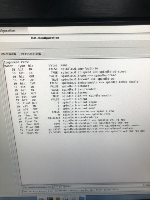
i attach the new .hal and .ini. and new halcmd results.
thank you guys so much for helping me.
Attachments:
Please Log in or Create an account to join the conversation.
- Michael
- Offline
- Platinum Member
-

Less
More
- Posts: 335
- Thank you received: 59
27 Nov 2021 17:58 - 27 Nov 2021 18:04 #227760
by Michael
Replied by Michael on topic cant regulate the 0-10V TB4 Spindle output from Mesa 7i76e
Lets just try getting it working in one direction to start:
comment out this by adding # to the front:
#net spindle-cw => hm2_7i76e.0.7i76.0.0.spindir
I would also keep:
OUTPUT_MIN_LIMIT = -24000
as
OUTPUT_MIN_LIMIT = 0
Since we are sure that this works as 0-10v and with a direction pin.
See what speed it turns now and what direction.
Also for argument sake you want speed in absolute terms so change this:
#net spindle-vel-cmd-rpm => pid.s.command
net spindle-vel-cmd-rpm-abs => pid.s.command
Also worth asking if you have any encoder feedback into the system. I think a second option would be to bypass the pid all together
Last edit: 27 Nov 2021 18:04 by Michael.
Please Log in or Create an account to join the conversation.
- Michael
- Offline
- Platinum Member
-

Less
More
- Posts: 335
- Thank you received: 59
27 Nov 2021 18:16 #227763
by Michael
Replied by Michael on topic cant regulate the 0-10V TB4 Spindle output from Mesa 7i76e
Just so its an option and since I wont be able to chime in till tomorrow. If you want to bypass the pid all together then you can disregard the last post and instead do the below.
comment out this by adding # to the front:
#net spindle-cw => hm2_7i76e.0.7i76.0.0.spindir
change
net spindle-output => hm2_7i76e.0.7i76.0.0.spinout
net spindle-vel-cmd-rpm-abs => hm2_7i76e.0.7i76.0.0.spinout
comment out this by adding # to the front:
#net spindle-cw => hm2_7i76e.0.7i76.0.0.spindir
change
net spindle-output => hm2_7i76e.0.7i76.0.0.spinout
net spindle-vel-cmd-rpm-abs => hm2_7i76e.0.7i76.0.0.spinout
Please Log in or Create an account to join the conversation.
- chris@cnc
- Offline
- Platinum Member
-

Less
More
- Posts: 529
- Thank you received: 140
27 Nov 2021 18:21 #227764
by chris@cnc
Replied by chris@cnc on topic cant regulate the 0-10V TB4 Spindle output from Mesa 7i76e
yes change
net spindle-cw => hm2_7i76e.0.7i76.0.0.spindir
to
net spindle-ccw => hm2_7i76e.0.7i76.0.0.spindir
second with M4 issue look here...
forum.linuxcnc.org/27-driver-boards/3874...-inverted-on-reverse
net spindle-cw => hm2_7i76e.0.7i76.0.0.spindir
to
net spindle-ccw => hm2_7i76e.0.7i76.0.0.spindir
second with M4 issue look here...
forum.linuxcnc.org/27-driver-boards/3874...-inverted-on-reverse
Please Log in or Create an account to join the conversation.
- FEMTO
-
 Topic Author
- Offline
- New Member
-

Less
More
- Posts: 8
- Thank you received: 0
28 Nov 2021 09:08 - 28 Nov 2021 09:46 #227805
by FEMTO
Replied by FEMTO on topic cant regulate the 0-10V TB4 Spindle output from Mesa 7i76e
i tried #net spindle-cw => hm2_7i76e.0.7i76.0.0.spindir and the spindle isn't turning in any direction.
Second option i did:
insert #
#net spindle-cw => hm2_7i76e.0.7i76.0.0.spindir
change
net spindle-output => hm2_7i76e.0.7i76.0.0.spinout
to
net spindle-vel-cmd-rpm-abs => hm2_7i76e.0.7i76.0.0.spinout
no spindle movement.
gone back to latest postet .hal file and
changed
net spindle-cw => hm2_7i76e.0.7i76.0.0.spindir
to
net spindle-ccw => hm2_7i76e.0.7i76.0.0.spindir
slow movement into the other direction than before.
also M4 issue isn't gone with
replacing
net spindle-vel-cmd-rpm => pid.s.command
with:
net spindle-vel-cmd-rpm-abs => pid.s.command
from the link.
Maybe it has something to do with the pncconf wizard problems i had. The wizard wasn't able to find the pins from the 7i76e Card i had a connection with. So i had copy and paste the most of the things in .hal file. Maybe there is something fundamental missing? i dont know.
Last edit: 28 Nov 2021 09:46 by FEMTO.
Please Log in or Create an account to join the conversation.
- PCW
-

- Offline
- Moderator
-

Less
More
- Posts: 17512
- Thank you received: 5118
28 Nov 2021 14:56 #227812
by PCW
Replied by PCW on topic cant regulate the 0-10V TB4 Spindle output from Mesa 7i76e
Yes, with net spindle-ccw => hm2_7i76e.0.7i76.0.0.spinena you will
this behaviour since the VFD will only be enabled when in reverse
(and you are not using the absolute commanded spindle speed so
you get full speed since the 7I76 expects a unsigned spindle speed )
this behaviour since the VFD will only be enabled when in reverse
(and you are not using the absolute commanded spindle speed so
you get full speed since the 7I76 expects a unsigned spindle speed )
Please Log in or Create an account to join the conversation.
- Michael
- Offline
- Platinum Member
-

Less
More
- Posts: 335
- Thank you received: 59
28 Nov 2021 18:33 - 28 Nov 2021 18:34 #227826
by Michael
Replied by Michael on topic cant regulate the 0-10V TB4 Spindle output from Mesa 7i76e
Something is probably not right with your drive our since you copied and pasted it could be an issue with the spindle scaling. The following should work. Basically all it does is send your commanded speed as an absolute value to the spinout which then creates voltage based off of scale.
#net spindle-output => hm2_7i76e.0.7i76.0.0.spinout
net spindle-vel-cmd-rpm-abs => hm2_7i76e.0.7i76.0.0.spinout
net spindle-enable => hm2_7i76e.0.7i76.0.0.spinena
net spindle-cw => hm2_7i76e.0.7i76.0.0.spindir
And then confirm these parameters with hal show. You may have an issue with copy and paste.
setp hm2_7i76e.0.7i76.0.0.spinout-minlim [SPINDLE_0]OUTPUT_MIN_LIMIT
setp hm2_7i76e.0.7i76.0.0.spinout-maxlim [SPINDLE_0]OUTPUT_MAX_LIMIT
setp hm2_7i76e.0.7i76.0.0.spinout-scalemax [SPINDLE_0]OUTPUT_SCALE
Also what is going on with Pin27 in the VFD drive? Why does that have +24v to it constantly as an input and is labeled "reset and coast" What exactly does that do and why is it always on?
Last edit: 28 Nov 2021 18:34 by Michael.
Please Log in or Create an account to join the conversation.
- PCW
-

- Offline
- Moderator
-

Less
More
- Posts: 17512
- Thank you received: 5118
28 Nov 2021 20:16 #227842
by PCW
Replied by PCW on topic cant regulate the 0-10V TB4 Spindle output from Mesa 7i76e
"with M3 active i get 0.7V between pin 55 and pin 50"
There are two issues here, the first is scaling/electrical issues
If you don't have a constant 10V between the VFDs pin50 and pin 55,
something is wrong electrically.
With 10V on pin 50 (and 7I76E TB4 pin 3) and 5000 RPM commanded
you should get 5000/24000 *10V = ~2.08V on pin
The second issue is that if you have a VFD that can only accept FWD/REV signals
and not ENA/DIR signals, an external circuit needs to be added to generate
the FWD/REV signals from the 7I76E's ENA/DIR signals. Normally this can be done
with a single SPDT relay
Please Log in or Create an account to join the conversation.
- FEMTO
-
 Topic Author
- Offline
- New Member
-

Less
More
- Posts: 8
- Thank you received: 0
28 Nov 2021 22:14 - 28 Nov 2021 22:46 #227851
by FEMTO
Replied by FEMTO on topic cant regulate the 0-10V TB4 Spindle output from Mesa 7i76e
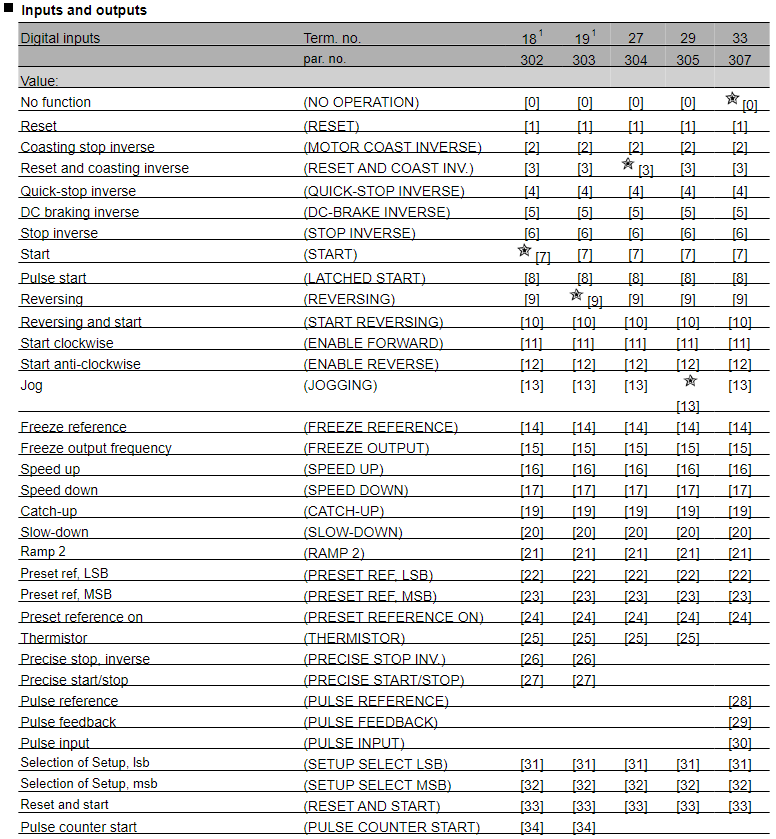
The 10V output from the VFD is stable at 10.4V until i give M3 or M4 command. After the command it drops down to 0.7V. Maybe this problem comes from the wrong input start signals for the VFD. There is a possibility to change the parameters for the pins on the VFD, maybe someone fits for the 7i76e. i attach the page from the manual. start clockwise and start anti-clockwise maybe?
I found the information for the pin 27 on another forum, its something like an enable signal for the remote control of the VFD. Without this i was far from spindle movement.
I found the information for the pin 27 on another forum, its something like an enable signal for the remote control of the VFD. Without this i was far from spindle movement.
Attachments:
Last edit: 28 Nov 2021 22:46 by FEMTO.
Please Log in or Create an account to join the conversation.
- tommylight
-

- Away
- Moderator
-

Less
More
- Posts: 21097
- Thank you received: 7205
28 Nov 2021 22:18 #227853
by tommylight
Replied by tommylight on topic cant regulate the 0-10V TB4 Spindle output from Mesa 7i76e
That points to wiring issues.The 10V output from the VFD is stable at 10.4V until i give M3 or M4 command. After the command it drops down to 0.7V.
Please Log in or Create an account to join the conversation.
Time to create page: 0.171 seconds


