
- Posts: 18115
- Thank you received: 5334
Fast Hole EDM from Hacked Parts
- PCW
- Offline
- Moderator
-

Less
More
1 year 10 months ago - 1 year 10 months ago #317650
by PCW
Replied by PCW on topic Fast Hole EDM from Hacked Parts
Yes, duty cycle is the correct pin.
Is the frequency reasonable and the valid bit set?
It sounds like the EDM output is single ended which means:
1. The EDM duty cycle output should connect to TB2 pin 13 (IDX+)
2. The EDM signal ground should connect to TB2 pin 15 (7I96S ground)
3. The 7I96S IDX input should be jumpered for TTL mode (W1 left)
4. 7I96S IDX- (TB2 pin 14) must be left unconnected
Note the if you connected the inputs to TB2 pins 13 and 14 without a ground
and ran the EDM system you may have damaged the EDM output or
7I96S input.
Last edit: 1 year 10 months ago by PCW.
- IronManDylan
- Offline
- Premium Member
-

Less
More
- Posts: 151
- Thank you received: 22
1 year 10 months ago #317680
by IronManDylan
Replied by IronManDylan on topic Fast Hole EDM from Hacked Parts
PCW,
I did that, why would it damage anything? Could a high voltage be carried through the ground wire to pin 14? This is the only thing that would make sense to me since the + wire is supposed to only be 3.3v..
Can you please explain what you mean by "Is the frequency reasonable and the valid bit set?"
Best,
-Dylan
- PCW
- Offline
- Moderator
-
Less
More
- Posts: 18115
- Thank you received: 5334
1 year 10 months ago - 1 year 10 months ago #317681
by PCW
Replied by PCW on topic Fast Hole EDM from Hacked Parts
EDM is very noisy and may have voltage spikes on the "ground"
that exceed the +-25V peak limitations of the 7I96S encoder
inputs.
Since it appears the you did not connect the grounds together there is
opportunity for these spikes to damage the 7I96 inputs. It may well be OK
but the way is was connected could not work.
I think you misunderstood the PWM output. It does no appear to be
a differential signal, so must connect to PWM --> IDX+ and GND --> GND
The frequency pin should show the current PWM frequency
The valid pin is true when the PWM frequency is above the
minimum frequency (basically a fault indication)
Last edit: 1 year 10 months ago by PCW.
- IronManDylan
- Offline
- Premium Member
-
Less
More
- Posts: 151
- Thank you received: 22
1 year 10 months ago #317682
by IronManDylan
Replied by IronManDylan on topic Fast Hole EDM from Hacked Parts
PCW,
Okay, lets hope nothing is fried. I will go try the outputs of PWM freq and valid now and report back.
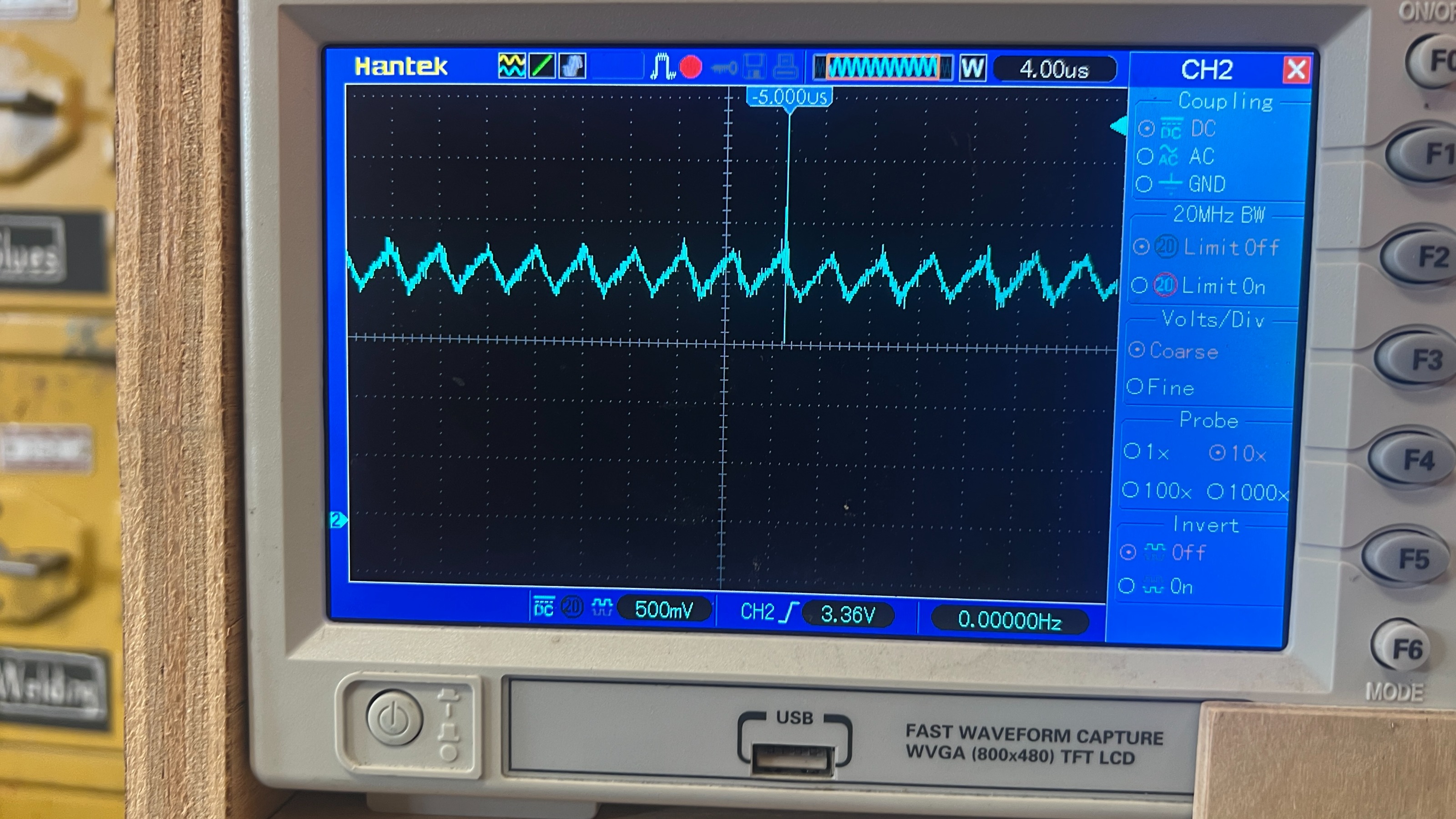
I got a chance to spend some time with the oscilloscope today am getting interesting behavior out of the EDM supply. What I am seeing is a sine wave that has an amplitude of about .5v. This entire sine wave moves up and down depending on the intensity of the EDM cut. At no cut it is at 0 volts and at short it is at 3.3v. In other words it seems to be behaving like an analog signal. It seems to me that will not work with the periodm func in mesa. I have contacted the creator of the Powercore EDM to see if this is the correct behavior or if something was damaged.
My alternative plan is to use an arduino that I have here to take the analog input and send it to the computer via USB to monitor cut duty cycle. Hopefully the python script that I am writing can accommodate communication with the arduino.
Okay, lets hope nothing is fried. I will go try the outputs of PWM freq and valid now and report back.
I got a chance to spend some time with the oscilloscope today am getting interesting behavior out of the EDM supply. What I am seeing is a sine wave that has an amplitude of about .5v. This entire sine wave moves up and down depending on the intensity of the EDM cut. At no cut it is at 0 volts and at short it is at 3.3v. In other words it seems to be behaving like an analog signal. It seems to me that will not work with the periodm func in mesa. I have contacted the creator of the Powercore EDM to see if this is the correct behavior or if something was damaged.
My alternative plan is to use an arduino that I have here to take the analog input and send it to the computer via USB to monitor cut duty cycle. Hopefully the python script that I am writing can accommodate communication with the arduino.
- IronManDylan
- Offline
- Premium Member
-
Less
More
- Posts: 151
- Thank you received: 22
1 year 10 months ago #317683
by IronManDylan
Replied by IronManDylan on topic Fast Hole EDM from Hacked Parts
The freq pin is 0 and the valid pin is false. So it appears that there is an issue with the PWM measuring.
- IronManDylan
- Offline
- Premium Member
-
Less
More
- Posts: 151
- Thank you received: 22
1 year 9 months ago #318477
by IronManDylan
Replied by IronManDylan on topic Fast Hole EDM from Hacked Parts
Hi all,
I have given up on trying to have a PID control of the feedrate. Instead I am using an arduino to set an input pin (hm2_7i96s.0.inm.00.input-10) to TRUE when the signal from the EDM power supply shows a short. I am able to confirm the pin is going TRUE using hal meter. That is the extent of my success.
I am trying to use this pin to set the feedrate into reverse when a short is detected using motion.adaptive-feed. However, absolutely nothing I do will work. I was trying to do this inside of the .hal file and that did not work. I also tried to do it in a python script and the GUI refused to load when this was attempted.
I really have no idea how to program linuxCNC and I am growing a little desperate and could really use some help. Could someone please walk me through how to use the input pin hm2_7i96s.0.inm.00.input-10 to toggle feedrate from forward to reverse. I feel like this should be straightforward but I am seriously struggling.
Thank you,
-Dylan
Time to create page: 0.439 seconds