Threading Index Varies With Speed
- 10K
-
 Topic Author
- Offline
- Premium Member
-

Less
More
- Posts: 142
- Thank you received: 33
26 Dec 2024 15:39 #317413
by 10K
Replied by 10K on topic Threading Index Varies With Speed
Removed setp from HAL file and retested. No change in observed behavior.
Yes, multiple passes at same speed are perfectly aligned with previous passes. This is true even when machine is turned off overnight and turned on next day (and re-homed). I don't think I'm losing pulses in the stepper motor. You can usually hear the motor miss pulses, and the results are reproducible.
10 count per turn encoder results in delta Y per pulse of 0.0125" for 8 TPI. Seems like the error would be less that that, and I'm seeing 0.085" error at 200 RPM.
Please Log in or Create an account to join the conversation.
- PCW
-

- Away
- Moderator
-

Less
More
- Posts: 17450
- Thank you received: 5091
26 Dec 2024 16:19 #317416
by PCW
Replied by PCW on topic Threading Index Varies With Speed
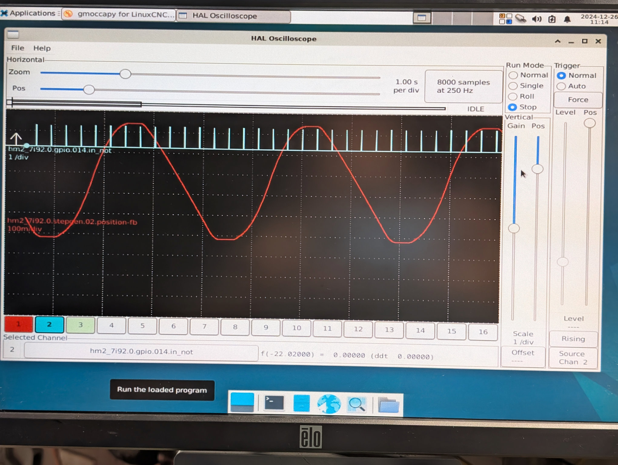
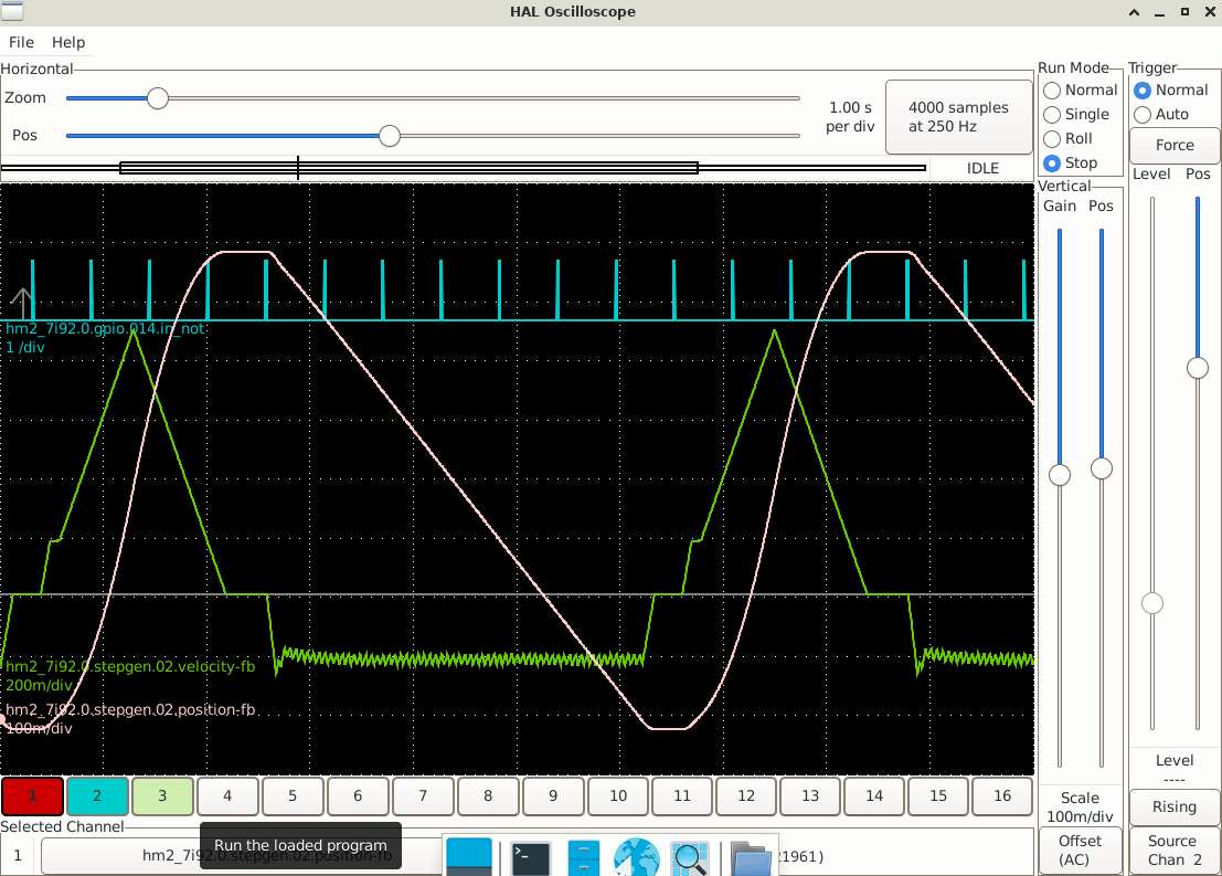
Looking at your pictures again, and they don't make sense...
The time between index pulses is ~1.2 seconds in both pictures = ~50 RPM
100 RPM would be 0.6 seconds per index, 200 would be 0.3
The time between index pulses is ~1.2 seconds in both pictures = ~50 RPM
100 RPM would be 0.6 seconds per index, 200 would be 0.3
Please Log in or Create an account to join the conversation.
- 10K
-
 Topic Author
- Offline
- Premium Member
-

Less
More
- Posts: 142
- Thank you received: 33
26 Dec 2024 18:06 #317424
by 10K
Replied by 10K on topic Threading Index Varies With Speed
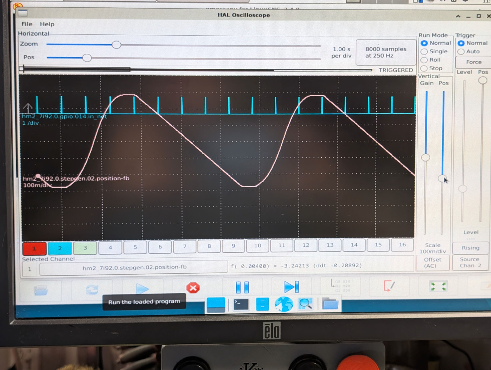
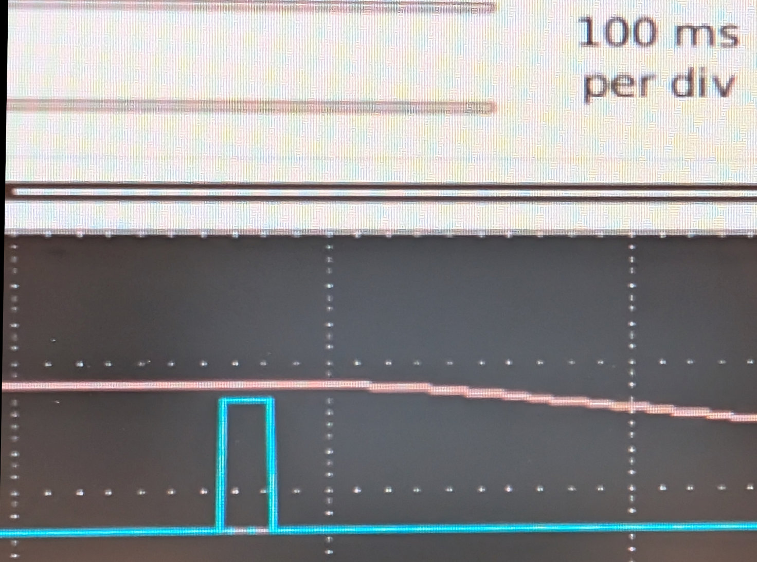
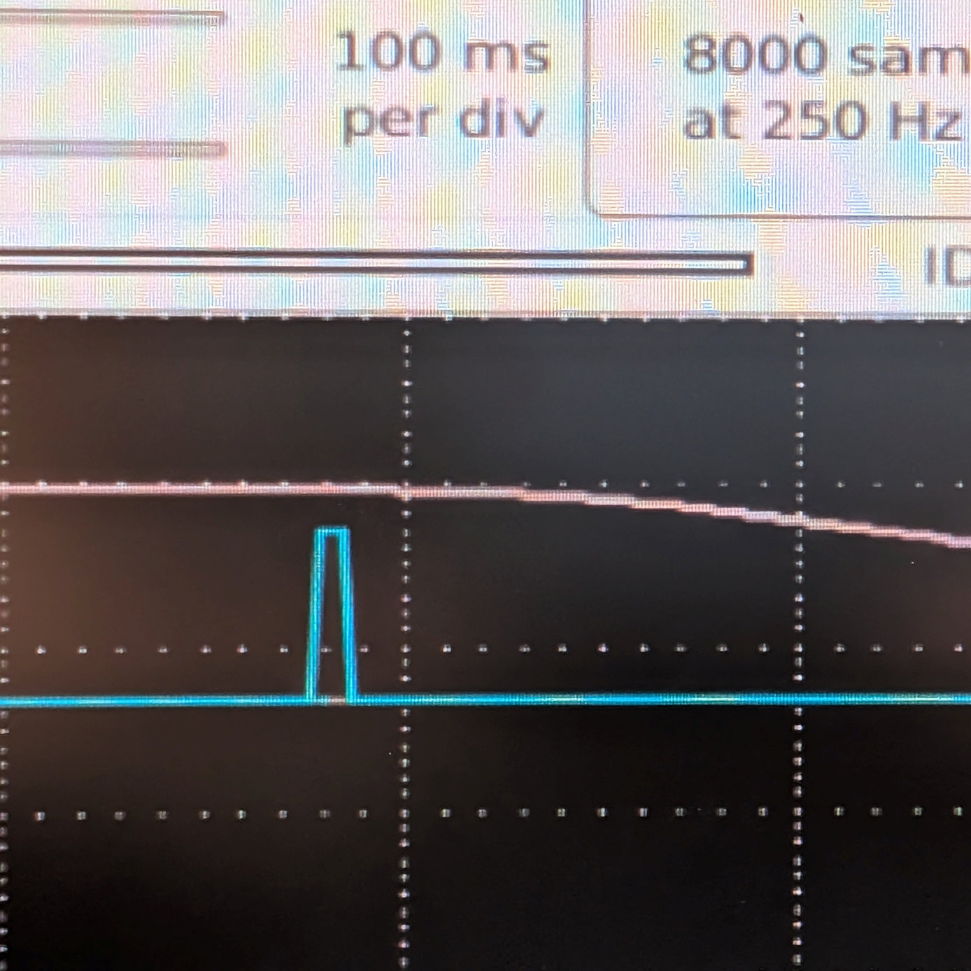
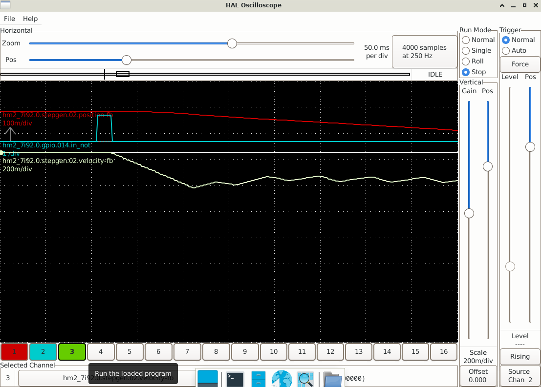
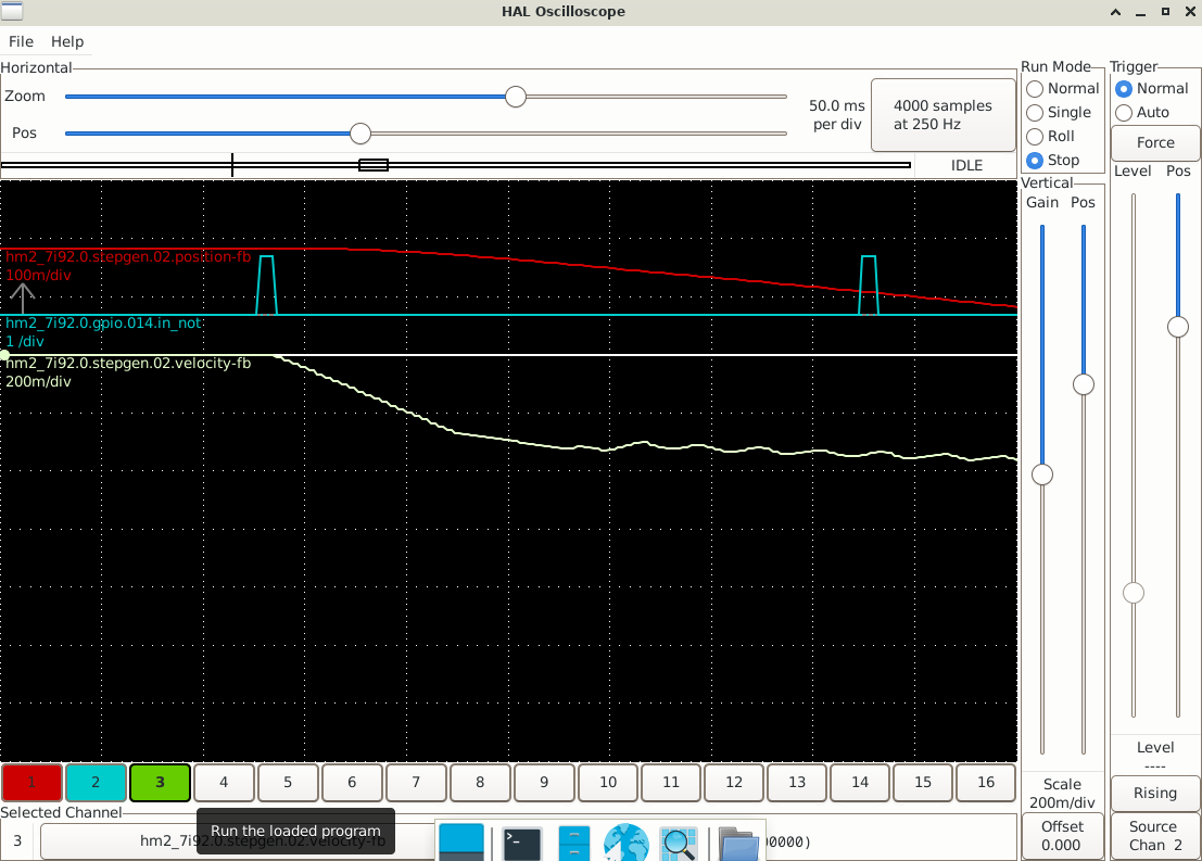
Good catch. I ran the test again, and noticed that HalScope does not update the picture except after every scan - that was probably the problem. I also made all the pictures at 100 ms per division. Here are the revised photos. I also made a zoomed in photo of when the movement starts, so I could read off the delay.I'm not sure if that has any significance.
100 RPM - 30ms from falling index to start of Z movement
200 RPM - 17ms from falling index to start of Z movement
100 RPM - 30ms from falling index to start of Z movement
200 RPM - 17ms from falling index to start of Z movement
Attachments:
Please Log in or Create an account to join the conversation.
- 10K
-
 Topic Author
- Offline
- Premium Member
-

Less
More
- Posts: 142
- Thank you received: 33
26 Dec 2024 20:18 #317432
by 10K
Replied by 10K on topic Threading Index Varies With Speed
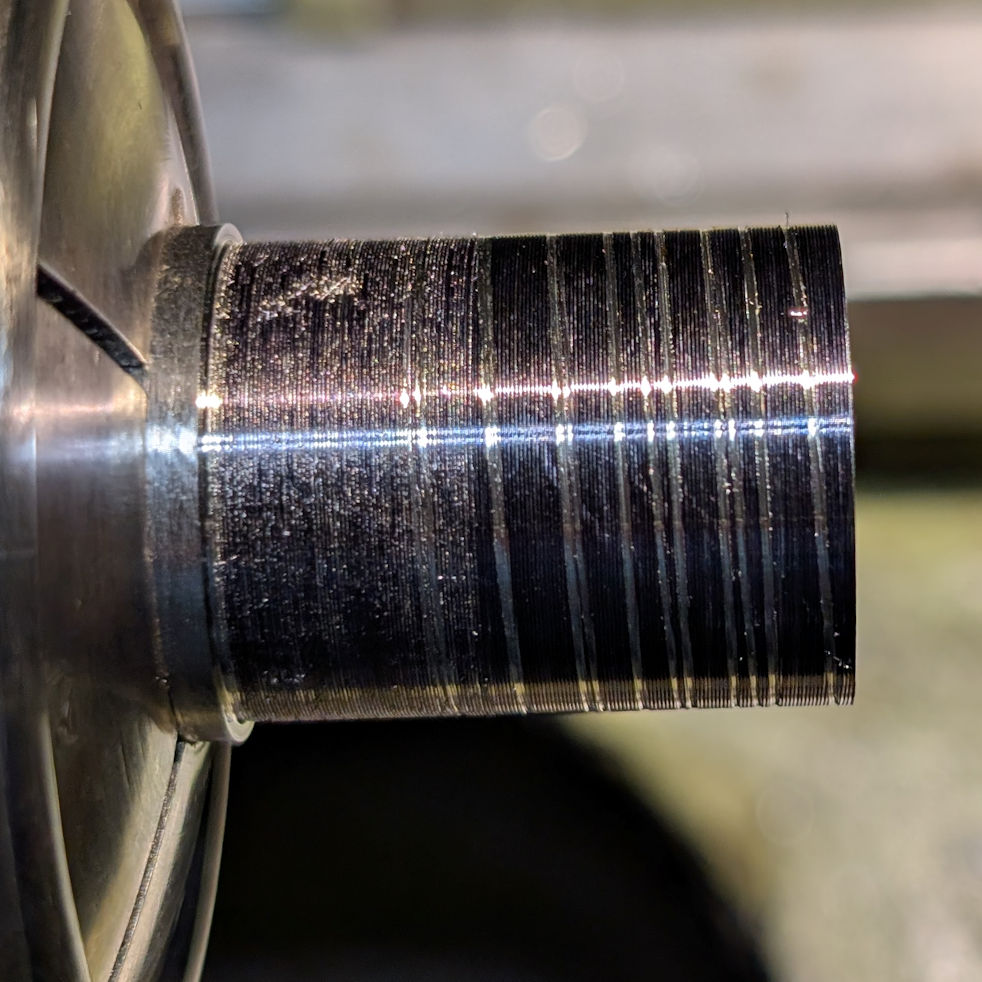
Here's another interesting example. I first made a threading scratch pass at 50 RPM. When the second pass started, I cranked the spindle speed quickly up to about 300 RPM (I'm guessing), then back to 50 RPM. The second cut started overlaying the first, then went to the right as the speed increased, then back to the original cut at the end.
So the speed definitely affects the Z position, and my original concern about the lathe bogging down during threading in a deep cut and then that slowdown causing gouging is warranted.
So the speed definitely affects the Z position, and my original concern about the lathe bogging down during threading in a deep cut and then that slowdown causing gouging is warranted.
Attachments:
Please Log in or Create an account to join the conversation.
- PCW
-

- Away
- Moderator
-

Less
More
- Posts: 17450
- Thank you received: 5091
26 Dec 2024 20:34 #317433
by PCW
Replied by PCW on topic Threading Index Varies With Speed
One thing on the plots, adding the Z velocity would make analysis easier.
Both in determining the start of motion and the point where Z motion
becomes synchronized with spindle rotation
Also an actual screenshot is easier to check than a picture because its
accurate and does not have geometric distortion. (making it hard to tell if
lines are straight)
Both in determining the start of motion and the point where Z motion
becomes synchronized with spindle rotation
Also an actual screenshot is easier to check than a picture because its
accurate and does not have geometric distortion. (making it hard to tell if
lines are straight)
Please Log in or Create an account to join the conversation.
- 10K
-
 Topic Author
- Offline
- Premium Member
-

Less
More
- Posts: 142
- Thank you received: 33
27 Dec 2024 15:20 #317480
by 10K
Replied by 10K on topic Threading Index Varies With Speed
Attachments:
Please Log in or Create an account to join the conversation.
- PCW
-

- Away
- Moderator
-

Less
More
- Posts: 17450
- Thank you received: 5091
27 Dec 2024 15:34 - 27 Dec 2024 15:49 #317482
by PCW
Replied by PCW on topic Threading Index Varies With Speed
The 100 RPM plot looks as expected, (It would probably be less jagged if the
interpolated encoder position was used) but the 200 RPM plot is definitely broken.
I don't understand the slow exponential velocity rise. Plotting the commanded velocity
would discriminate between LinuxCNC motion issues and hardware side issues.
Also , plotting the spindle position might help the diagnosis.
I would try doubling the acceleration to see if that helps (Increasing the acceleration
may _require_ using interpolated spindle position as the large Z position staircase
from having only 10 counts/turn will be less filtered.)
Last edit: 27 Dec 2024 15:49 by PCW.
Please Log in or Create an account to join the conversation.
- 10K
-
 Topic Author
- Offline
- Premium Member
-

Less
More
- Posts: 142
- Thank you received: 33
27 Dec 2024 19:58 #317505
by 10K
Replied by 10K on topic Threading Index Varies With Speed
Here's the values for Z:
MAX_VELOCITY = 1.8
MAX_ACCELERATION = 2.0
These were set after a lot of experimentation. Higher values stall the stepper motor. I could try increasing the acceleration somewhat, but probably in the 10-20% range. Not sure this would make much difference. Let me know if you think I should try it anyway.
You mentioned that the 200 RPM plot is broken. Are you referring to the change of slope in the velocity before it starts oscillating?
Is it likely that the 10 pulse/revolution pulses are causing the problem? I could redo that part of the lathe. Getting greater acceleration will require a new stepper or servo motor and a lot of work.
I have two choices for the encoder-
1) I have some encoders in my junk drawer. They're both quadrature. One is a US Digital 1000 pulses/rev with a separate index signal, and the other is a more robust looking Accu-coder 2500 pulses/rev. Both are designed for small shafts, so I'd need a belt or gearing to connect them.
2) I could machine a gear to bolt on the spindle pulley. It'd be about 7 1/4" or so in diameter, so how ever many teeth I could fit on it. Maybe about 90 1/8" teeth? Or 180 1/16" teeth? I don't have any feel for how many pulses/revolution is appropriate, so maybe this would not work.
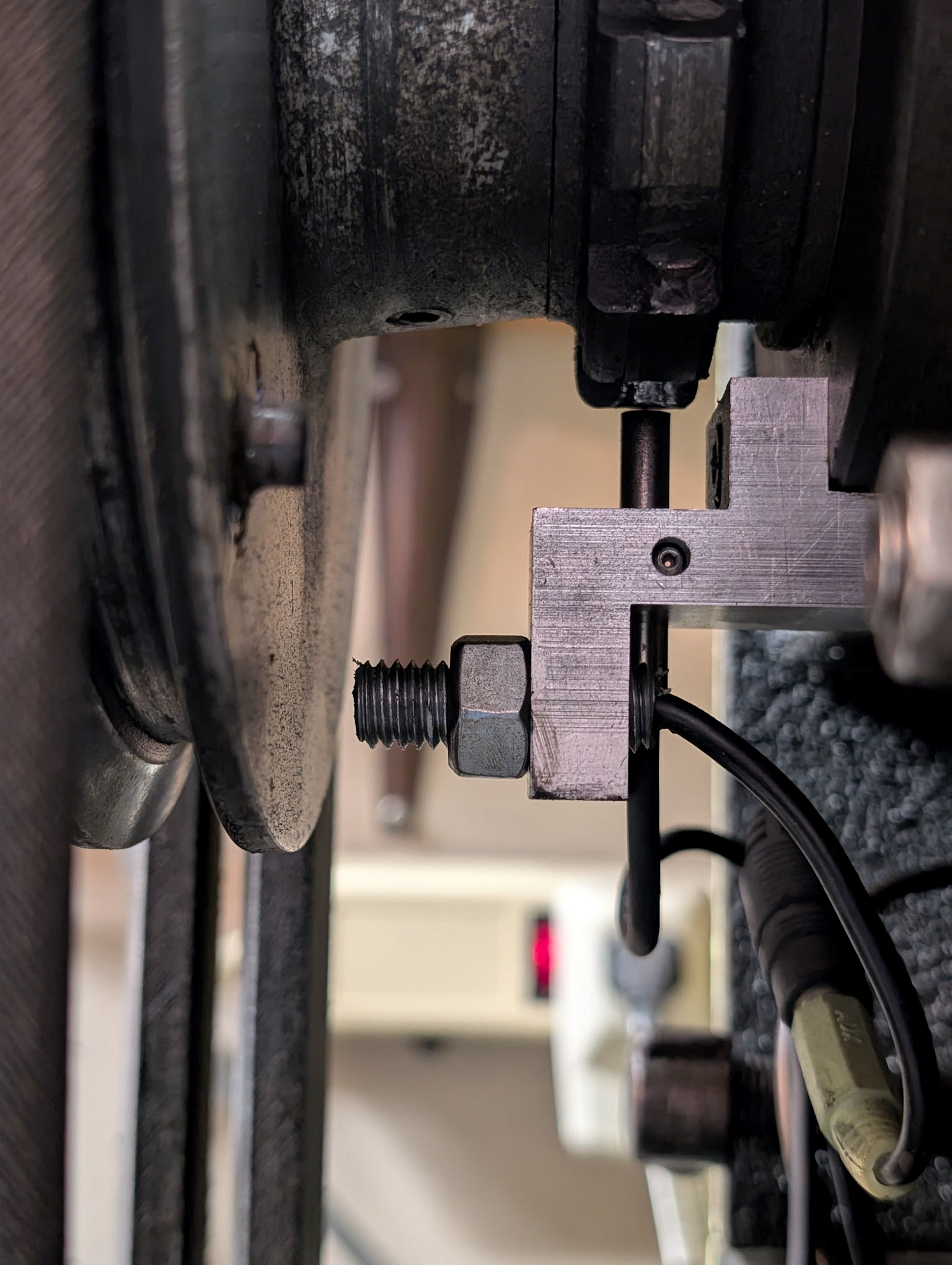
Here's a photo of the two pulse generators. The 1 pulse/rev is magnetic and the other one is proximity. The teeth are for locking the spindle.
Attachments:
Please Log in or Create an account to join the conversation.
- PCW
-

- Away
- Moderator
-

Less
More
- Posts: 17450
- Thank you received: 5091
27 Dec 2024 20:59 #317506
by PCW
Replied by PCW on topic Threading Index Varies With Speed
You mentioned that the 200 RPM plot is broken. Are you referring to the change of slope in the velocity before it starts oscillating?
No, I am referring to the fact that it never reaches a constant velocity but seems to only exponentially approach a constant velocity, I am ignoring the sawtooth velocity waveform,. You should be able to get rid of most of the sawtooth by using the interpolated encoder position (so the position is updated every ms rather than every encoder slot)
No, I am referring to the fact that it never reaches a constant velocity but seems to only exponentially approach a constant velocity, I am ignoring the sawtooth velocity waveform,. You should be able to get rid of most of the sawtooth by using the interpolated encoder position (so the position is updated every ms rather than every encoder slot)
Please Log in or Create an account to join the conversation.
- cmorley
- Offline
- Moderator
-

Less
More
- Posts: 7239
- Thank you received: 2107
27 Dec 2024 21:10 #317507
by cmorley
Replied by cmorley on topic Threading Index Varies With Speed
Why do you think that spindle speed is uncoupled from spindle sync position?
look in tp.c at tpSyncPositionMode()
Now I don't understand the code completely but I think the general idea is to:
-accelerate (at max) the axis to match the calculated spindle speed for the requested units per revolution.
-when it is synced speed then maintain the sync.
With a fixed acceleration rate, a faster spindle will take longer to sync speed.
To have threads always match you would need to also sync position and probably with a longer section of out of spec threads. I see no indication of position tracking
So I think it's a feature not a bug.
Please Log in or Create an account to join the conversation.
Time to create page: 0.213 seconds

