bandit controller retrofit
- langdons
-

- Offline
- Platinum Member
-

Less
More
- Posts: 776
- Thank you received: 93
28 Mar 2025 13:51 #325161
by langdons
Replied by langdons on topic bandit controller retrofit
The controller I linked to gives a max RMS current of about 6A.
This one is on sale for 80% off!
www.aliexpress.com/item/1005005291871448.html
Max RMS current is about 5A.
(After I've already purchased it, of course)
I am very, very unlucky
This one is on sale for 80% off!
www.aliexpress.com/item/1005005291871448.html
Max RMS current is about 5A.
(After I've already purchased it, of course)
I am very, very unlucky
Please Log in or Create an account to join the conversation.
- tommylight
-

- Offline
- Moderator
-

Less
More
- Posts: 21053
- Thank you received: 7181
28 Mar 2025 15:01 #325165
by tommylight
There are also 3 phase and 5 phase stepper motors, Vexta had some nice videos explaining all the types and versions on youtube.
Replied by tommylight on topic bandit controller retrofit
They always are 8 wire inside, they all have 4 windings inside, they all have 50 magnetic de-tents inside, making it 200 steps per revolution. There are same types with 400 steps per revolution, meaning 0.9 degree per step instead of the usual 1.8 degree per step.I know they are 6-wire, but perhaps they are 8-wire internally.
There are also 3 phase and 5 phase stepper motors, Vexta had some nice videos explaining all the types and versions on youtube.
The following user(s) said Thank You: Masiwood123
Please Log in or Create an account to join the conversation.
- langdons
-
- Offline
- Platinum Member
-
Less
More
- Posts: 776
- Thank you received: 93
28 Mar 2025 15:36 #325169
by langdons
Replied by langdons on topic bandit controller retrofit
To OP:
Buy some cheapo stepper driver and try it out.
It only costs 23CAD (16USD).
www.aliexpress.com/item/1005005291871448.html
Set it to max current setting, with 800 steps/rev
Buy some cheapo stepper driver and try it out.
It only costs 23CAD (16USD).
www.aliexpress.com/item/1005005291871448.html
Set it to max current setting, with 800 steps/rev
The following user(s) said Thank You: Masiwood123
Please Log in or Create an account to join the conversation.
- Masiwood123
-
 Topic Author
- Away
- Platinum Member
-
Less
More
- Posts: 408
- Thank you received: 90
28 Mar 2025 19:46 #325183
by Masiwood123
Replied by Masiwood123 on topic bandit controller retrofit
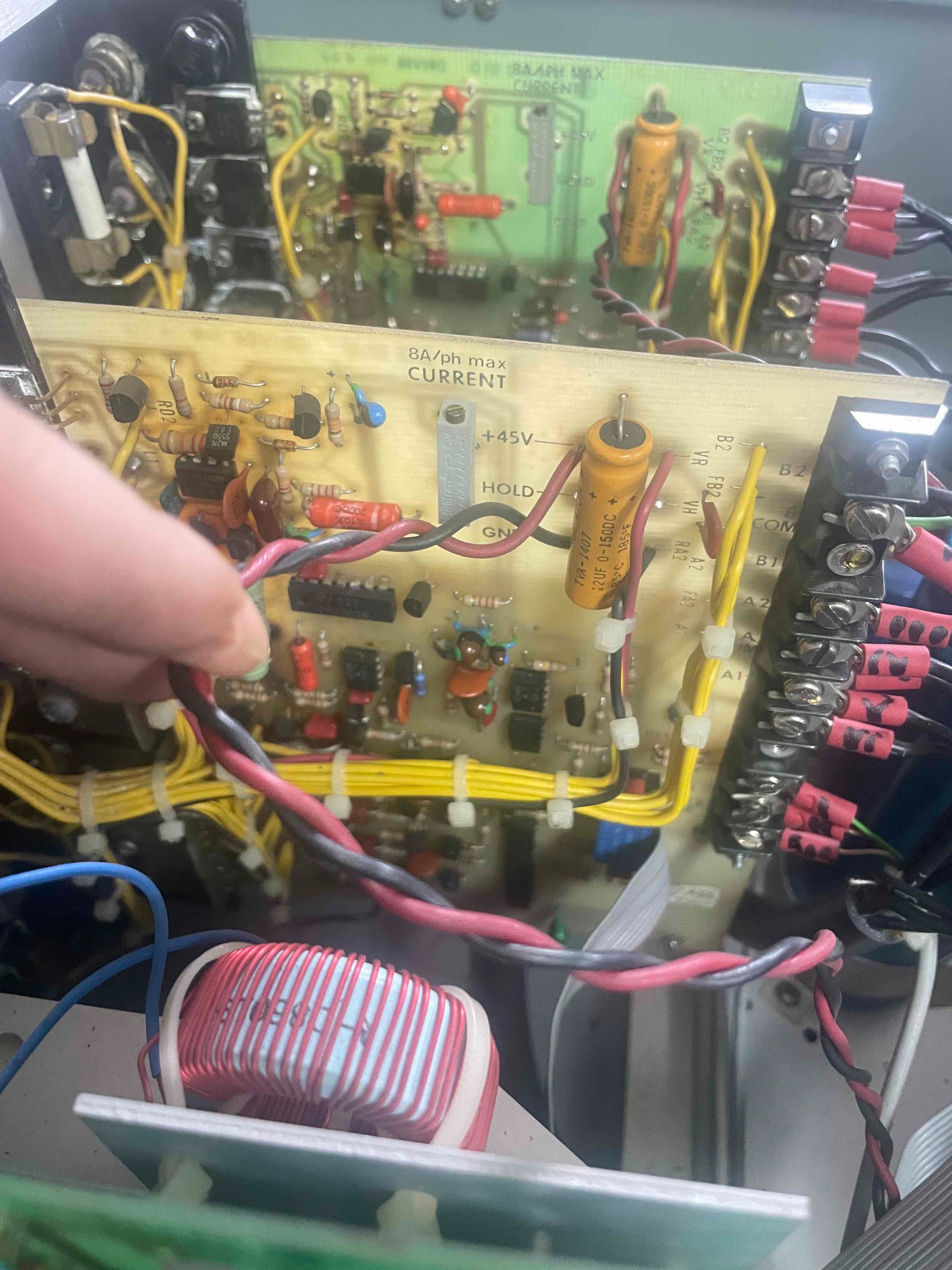
thank you guys, you helped me a lot, I realized that these are in fact stepper drivers and motors, the voltage is 45vdc, I will buy a simple stepper driver and try to connect phases a,a+,b,b+ and according to my understanding ``com'' I should short-circuit two pairs (wires) of aCOM and bCOM separately
Attachments:
Please Log in or Create an account to join the conversation.
- tommylight
-
- Offline
- Moderator
-
Less
More
- Posts: 21053
- Thank you received: 7181
28 Mar 2025 20:06 - 28 Mar 2025 20:07 #325188
by tommylight
Replied by tommylight on topic bandit controller retrofit
Do NOT use the COM motor wires on new drives!!!
Do NOT use 5 wire stepper motors with new drives!!!
New drives are always "bipolar" meaning each winding has it's own H-bridge.
Old drives were "unipolar" meaning each winding was driven by a single transistor/MOSFET to ground, while all 4 pins from one side of all 4 windings was wired to + (positive) of the power supply.
Use a DVM in OHM or BEEP mode to find out what wires belong to the same winding, and based on resistance you can also figure out the middle wire, see bellow:
-if you want max torque but lower rotation speed, use the two wires with most resistance, in your case use A1/A2 and B1/B2 and leave ACOM/BCOM unconnected. Do isolate them so they do not touch.
-if you want more speed at lower torque, use the middle wire and 1 of the remaining 2 wires, it does not matter which one, just one.
Last edit: 28 Mar 2025 20:07 by tommylight. Reason: more info
The following user(s) said Thank You: Masiwood123
Please Log in or Create an account to join the conversation.
- Masiwood123
-
Topic Author
- Away
- Platinum Member
-
Less
More
- Posts: 408
- Thank you received: 90
28 Mar 2025 20:19 #325189
by Masiwood123
Replied by Masiwood123 on topic bandit controller retrofit
``if you want max torque but lower rotation speed, use the two wires with most resistance, in your case use A1/A2 and B1/B2 and leave ACOM/BCOM unconnected``
Thanks a lot Tom, will check first, exactly what you said, that is how i wanted to connect.
Thanks a lot Tom, will check first, exactly what you said, that is how i wanted to connect.
The following user(s) said Thank You: tommylight
Please Log in or Create an account to join the conversation.
- tommylight
-
- Offline
- Moderator
-
Less
More
- Posts: 21053
- Thank you received: 7181
28 Mar 2025 20:24 #325191
by tommylight
Replied by tommylight on topic bandit controller retrofit
The 3 bottom wires on the drive boards, what do they have written ?
Do you have an old PC with parallel port?
If those wires are step/dir and GND, fire up the PC, wire some wires from parallel port to those 3 wires, move the machine!
Do you have an old PC with parallel port?
If those wires are step/dir and GND, fire up the PC, wire some wires from parallel port to those 3 wires, move the machine!
The following user(s) said Thank You: Masiwood123
Please Log in or Create an account to join the conversation.
- Masiwood123
-
Topic Author
- Away
- Platinum Member
-
Less
More
- Posts: 408
- Thank you received: 90
28 Mar 2025 20:49 #325194
by Masiwood123
Replied by Masiwood123 on topic bandit controller retrofit
I don't think they are, but I'll check, I think the ones from each driver go to the ``estop'' system of the machine or to the end switches, something like that... the signals are in this flat ribbon cable, but who knows what they are, maybe some older control system, some ttl something, I wouldn't know how to check that without schematic , and I couldn't find a schematic for this driver, the controller is from the 70s.
Please Log in or Create an account to join the conversation.
- tommylight
-
- Offline
- Moderator
-
Less
More
- Posts: 21053
- Thank you received: 7181
28 Mar 2025 23:27 #325203
by tommylight
Replied by tommylight on topic bandit controller retrofit
To the left of the ribbon cable, are those optocouplers?
If yes, see what wires go to those optos inputs, those should be step, dir, and maybe enable, one is ground, and for testing you only need 1, the step pin, and if used the enable, but if the drives lock when powered on, then skip enable as they are enabled, so use a signal generator or parallel port, or a small crappy transformer that outputs 3 to 6V AC, should be enough to check if they work, and if they do, leave them on.
Be aware that some older drives use two inputs as step and have no dir at all, so steps on one pin turn the motor one direction, while steps on other pin move motor the other direction.
There are also "quadrature inputs" using steps on both pins, but 90 degrees between them, also no dir.
And as the last type, the 4 input ones, so when testing if the motor does not turn but just vibrates in place, check other pins, there should be 4 that cause the motor to vibrate.
All of those can be controlled by LinuxCNC, even through a parallel port, hence my hesitation to change the drives.
But if you think the time is more valuable, do change them.
And if the motors turn out to be 5 wire ones, they can be changed to bipolar, just require a bit of time and a soldering iron.
BTW, never ever remove the rotor from the stator on stepper motors, that will render them useless as they will de-magnetize.
The following user(s) said Thank You: Masiwood123
Please Log in or Create an account to join the conversation.
- langdons
-
- Offline
- Platinum Member
-
Less
More
- Posts: 776
- Thank you received: 93
29 Mar 2025 01:56 #325220
by langdons
Replied by langdons on topic bandit controller retrofit
8A peak current.
Get one of these (or 3, considering they are essentially free):
www.aliexpress.com/item/1005005291871448.html
Get one of these (or 3, considering they are essentially free):
www.aliexpress.com/item/1005005291871448.html
The following user(s) said Thank You: Masiwood123
Please Log in or Create an account to join the conversation.
Time to create page: 0.096 seconds