Mesa 5i25+7i77 plug-n-go configuration
- 33zy
- Offline
- Junior Member
-

Less
More
- Posts: 27
- Thank you received: 2
07 Dec 2014 09:11 #53780
by 33zy
Replied by 33zy on topic Mesa 5i25+7i77 plug-n-go configuration
I have BE25A20C drives. I have moved dip switch 7 because I don't have a HAL input.
1) turn on Linux
2) CLICK the "soft" machine power
the drive enables, led goes green
the mill table moves a tiny bit
I get: (X) joint 0 following error
ideas? or things I should check first?
1) turn on Linux
2) CLICK the "soft" machine power
the drive enables, led goes green
the mill table moves a tiny bit
I get: (X) joint 0 following error
ideas? or things I should check first?
Please Log in or Create an account to join the conversation.
- PCW
-

- Away
- Moderator
-

Less
More
- Posts: 18888
- Thank you received: 5213
07 Dec 2014 10:24 - 07 Dec 2014 10:31 #53781
by PCW
Replied by PCW on topic Mesa 5i25+7i77 plug-n-go configuration
If this is a first time setup you have a 50% chance of getting the feedback backwards
When the servo feedback is backwards the drives will runaway as soon as enabled if P or I or D are large enough,
causing an immediate following error (this following error disabling the drives is a _good thing_ otherwise
they might have run into the stops at full speed)
If the encoder feedback direction is correct (DRO readouts change in the correct direction when the axis are moved by hand)
you will need to reverse the analog output polarity.
Last edit: 07 Dec 2014 10:31 by PCW.
Please Log in or Create an account to join the conversation.
- 33zy
- Offline
- Junior Member
-
Less
More
- Posts: 27
- Thank you received: 2
08 Dec 2014 06:33 - 08 Dec 2014 06:43 #53799
by 33zy
Replied by 33zy on topic Mesa 5i25+7i77 plug-n-go configuration
Thank you PCW. When you say Servo feedback does that mean encoder?
I have US digital differential encoders.
A(-)
A(+)
GND
B(-)
B(+)
+5
index (-)
index(+)
The BE25A20AC
1)nc
2)CHANNEL A
3)nc
4)CHANNEL B
5)SIGNAL GROUND
I currently have the A(+) = channelA and B(+) =channelB
The encoder read out on the screen moves the correct direction as the table
I switched A & B but I still get the error, maybe I have misinterpreted your sugestion
Last edit: 08 Dec 2014 06:43 by 33zy.
Please Log in or Create an account to join the conversation.
- PCW
-
- Away
- Moderator
-
Less
More
- Posts: 18888
- Thank you received: 5213
08 Dec 2014 07:24 #53800
by PCW
Replied by PCW on topic Mesa 5i25+7i77 plug-n-go configuration
OK First, you should absolutely expect following errors when you first start to setup the drives
This can happen because the feedback is backwards so you get an immediate runaway or because you have no
feedback and the drives drift until the distance is as large as the following error setting
Also you drives may just runaway in any case if they are setup for velocity mode and you dont have tachometer feedback
Normally when first tuning you will need to widen the ferror limits to say 1 inch so you can see whats going on
If the DRO readout is in the correct direction, dont swap encoder wires to fix backwards feedback
you change the analog output polarity to fix this, for example changing
hm2_5i25.0.7i77.0.1.analogout0-scalemax 10
to
hm2_5i25.0.7i77.0.1.analogout0-scalemax -10
will reverse the output polarity of analog channel 0 on a 7I77
Please Log in or Create an account to join the conversation.
- 33zy
- Offline
- Junior Member
-
Less
More
- Posts: 27
- Thank you received: 2
08 Dec 2014 23:51 #53822
by 33zy
Replied by 33zy on topic Mesa 5i25+7i77 plug-n-go configuration
I changed the polarity in the ".ini", no luck. My next plan is to test the drive independent of the 7i77, maybe I have the drive (BE25A20C) configured wrong.
I attached my hal and ini, its very possible I am making a basic error on the software side also.
I attached my hal and ini, its very possible I am making a basic error on the software side also.
Please Log in or Create an account to join the conversation.
- 33zy
- Offline
- Junior Member
-
Less
More
- Posts: 27
- Thank you received: 2
21 Dec 2014 08:44 #54180
by 33zy
Replied by 33zy on topic Mesa 5i25+7i77 plug-n-go configuration
When I soft enable the be25ac20 drive goes green indicating that it has been enabled.
The 7i77 TB5 aout0 reads 1.43 volts?
The 7i77 TB5 gnd reads 0
This appears to be enough for the motor driver to start the servo, because it runs away only to be stopped with "joint following error"
Why would the auot0 be giving me 1.43 if no motion was commanded?
The 7i77 TB5 aout0 reads 1.43 volts?
The 7i77 TB5 gnd reads 0
This appears to be enough for the motor driver to start the servo, because it runs away only to be stopped with "joint following error"
Why would the auot0 be giving me 1.43 if no motion was commanded?
The following user(s) said Thank You: new2linux
Please Log in or Create an account to join the conversation.
- PCW
-
- Away
- Moderator
-
Less
More
- Posts: 18888
- Thank you received: 5213
21 Dec 2014 11:50 #54181
by PCW
Replied by PCW on topic Mesa 5i25+7i77 plug-n-go configuration
If AOUT0 (TB5 pin 4 = fourth from bottom measured relative to pin 3) is 1.43V when disabled
(linuxcnc is not running) and you have disconnected all connections to
external hardware, this indicates a bad 7I77.
if it only happens when you enable linuxcnc, its most likely feedback related
and you will have to trace the PID inputs and output with halmeter to figure out what
is going on (you may also have to widen the ferror limits so see whats happening)
The other thing to try is the open loop test in pncconf and seen if you can make the
motors run each direction (beware that this may runaway)
The following user(s) said Thank You: new2linux
Please Log in or Create an account to join the conversation.
- 33zy
- Offline
- Junior Member
-
Less
More
- Posts: 27
- Thank you received: 2
22 Dec 2014 02:26 #54194
by 33zy
Replied by 33zy on topic Mesa 5i25+7i77 plug-n-go configuration
I am pretty green at this,
When we say feedback, I associate that with the encoder.
The encoder apears to function, I see the icon move when I spin encoder by hand.
Since it is the 7i77 that is supplying signal to the driver, (1.43) what other "feedbacks" could I be messing up? Have I missed an entire wire group?
The feedback to the driver, I pulled from the encoder bank on 7i77
All my signal grounds go to 7i77 field ground.
Is thier a list of PID inputs & outputs I should start checking. I am not sure how many thier are total?
The following user(s) said Thank You: new2linux
Please Log in or Create an account to join the conversation.
- PCW
-
- Away
- Moderator
-
Less
More
- Posts: 18888
- Thank you received: 5213
22 Dec 2014 02:49 - 22 Dec 2014 02:51 #54195
by PCW
Replied by PCW on topic Mesa 5i25+7i77 plug-n-go configuration
First: did you measure the voltage between TB5 pin 4 (AOUT0 ) and TB5 pin 3 (ANALOG GND) with linuxcnc not running?
and all TB5 connections disconnected? If this is not very close to 0V, (and 7I77 5V is OK) there is a hardware problem with the 7I77
Second: Field I/O ground should normally have NO connections to the analog I/O section of the 7I77.
analog wiring is all to TB5
AOUTN --> DRIVE AIN+
GNDN --> DRIVE AIN- or DRIVE ANALOG GND
GNDN is next to AOUTN on TB5
Last edit: 22 Dec 2014 02:51 by PCW.
The following user(s) said Thank You: new2linux
Please Log in or Create an account to join the conversation.
- 33zy
- Offline
- Junior Member
-
Less
More
- Posts: 27
- Thank you received: 2
23 Dec 2014 00:46 #54227
by 33zy
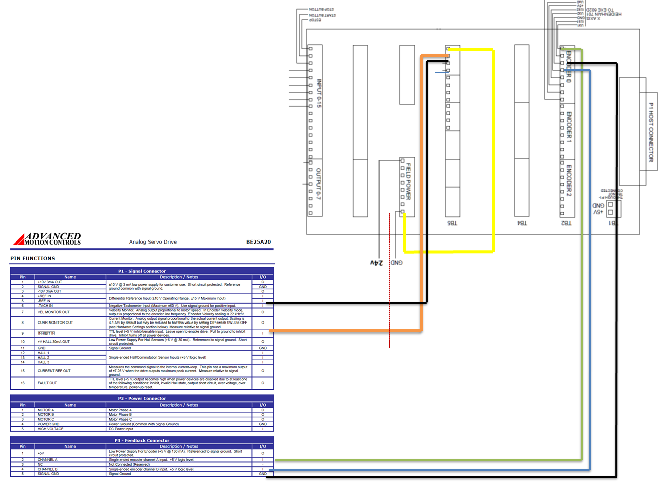
I have attached a illustration of how I wired it.
It sounds like I should have the #11 signal ground on the TB5 gnd, the same location i have the #5(-ref in)?
Replied by 33zy on topic Mesa 5i25+7i77 plug-n-go configuration
I have attached a illustration of how I wired it.
It sounds like I should have the #11 signal ground on the TB5 gnd, the same location i have the #5(-ref in)?
Please Log in or Create an account to join the conversation.
Moderators: cmorley
Time to create page: 0.091 seconds