Configuration 7i92m_7i76x1D

More
8 years 8 months ago #105979 by aleksamc
It will not be problem if I will connect Step+ to step+ and Step- to Gnd? In the EP1C manual on page 14 says that I need to use resistor 85-120 Ohm. I tried this connection with resistor 100 Ohm but unsuccessful.

Please Log in or Create an account to join the conversation.
More
8 years 8 months ago - 8 years 8 months ago #105980 by PCW
Replied by PCW on topic Configuration 7i92m_7i76x1D
As long as you do not connect any of the 7I76 step/dir signals to ground (or 5V) that's OK

So for single ended with common anode Opto in drive:

7I76 step- to drive step-
7I76 +5 to drive step+
7I76 step+ and GND unconnected

and for single ended common cathode Opto in drive:

7I76 step+ to drive step+
7I76 GND to drive step-
7I76 step- and +5V unconnected

And lastly for differential:

7I76 step+ to drive step+
7I76 step- to drive step-
Last edit: 8 years 8 months ago by PCW.

Please Log in or Create an account to join the conversation.
More
8 years 8 months ago #105983 by aleksamc
Hear I have differential input and it doesn't work.
Could be possible, that I somehow dameged inputs of step/dir signals? For example pluged off singal cable when servos was turned on? I don't remember that I do that, because I try to use them very gently, but for example.

Please Log in or Create an account to join the conversation.

More
8 years 8 months ago #105984 by PCW
Replied by PCW on topic Configuration 7i92m_7i76x1D
Its very unlikely you have damaged the step/dir inputs unless you connected them to 24V or something like that
Since they are opto-isolated, even live connecting them should not be harmful

Please Log in or Create an account to join the conversation.

More
8 years 8 months ago #106064 by aleksamc
We also have one more servo drive EP3, of the same vendor but it’s older then those. I used same cable and same connection as for previouse drivers. And it works fine. I’ve concluded that it’s problem of all servo drives. I’ve opened it, it seems, that all step/dir signals comes to micro scheme P2160 1646 with 8 pins. I didn’t find datasheet for it. I’ve opened good one, it uses 074H 1516 txp also with 8 pins.
Then I’ve connected to my servo drives 24V encoder throughout resistors 1,5kOhm in single scheme and it worked fine. I see that I need to make some optocoupled PCB board to connect to MESA and use 24V simultaneously. It will solve my problem.
Thank you for your time, Peter, and for your message as Mesa tech specialist. You’ve helped me great.

Please Log in or Create an account to join the conversation.

More
8 years 8 months ago #106624 by aleksamc
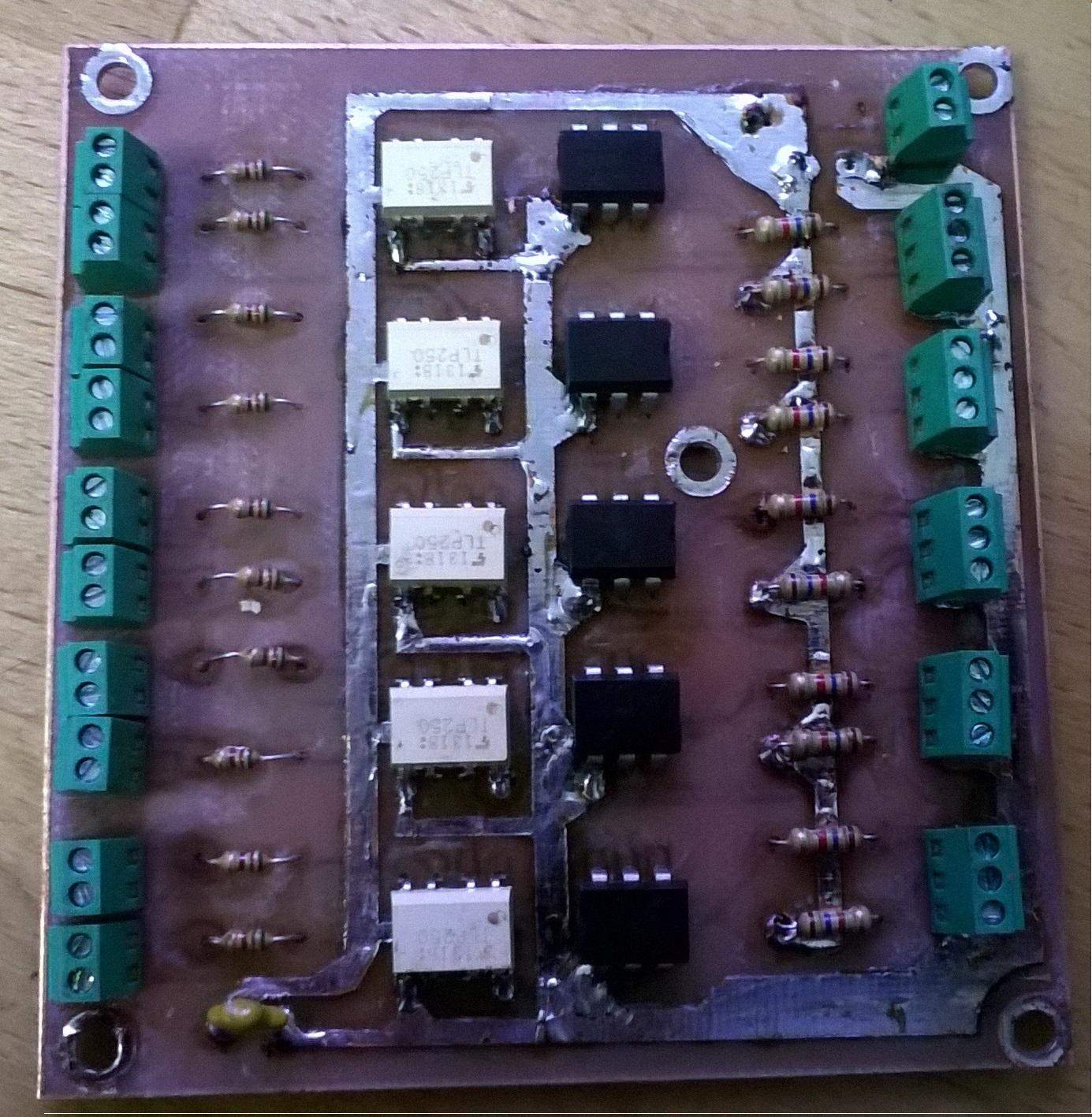
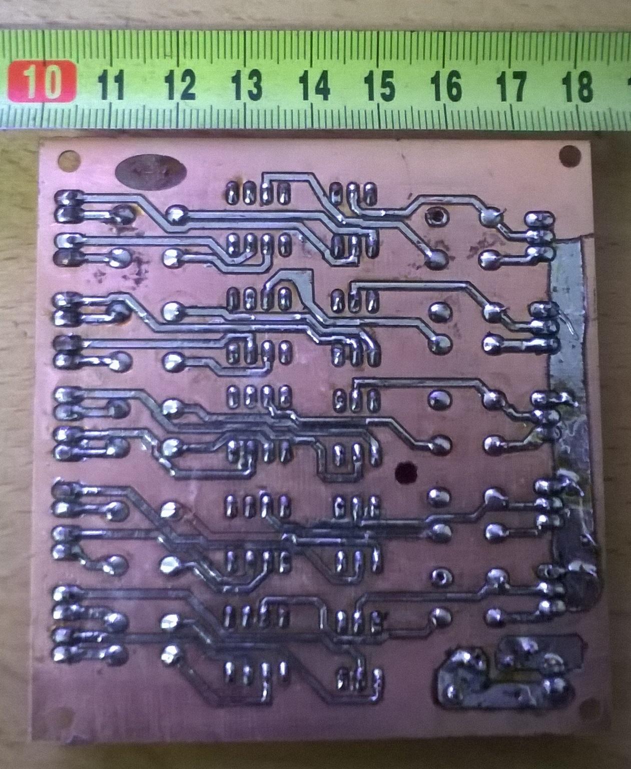
I've finished my "5V to 24V" transmitter for 5 chanels and it works fine.
For step signal I use TLP250 - high freaquencu optocoupler and for Dir signal I use cheap and "slow" 4N27 transistor optocoupler.

I also have problems with only one X axis (port 0). It has big ripple. It's so big that I see that direction changes 7-10 times. I've also connected diode to MESA 7i76 output to check if problem in my pcb or MESA

File Attachment:

File Name: MachineCNC...2-27.hal
File Size:19.84 KB

File Attachment:

File Name: MachineCNC...2-27.ini
File Size:5.3 KB
. Ripple goes from MESA side. It seems that problem in PID requlator. But parameters for X, Y and Z are same. I attach also Hal and ini files. Please look them. I think that problem in configuration files.

Please Log in or Create an account to join the conversation.

Moderators: cmorley
Time to create page: 0.109 seconds
Powered by Kunena Forum
