Configuration 7i92m_7i76x1D
- Todd Zuercher
-

- Offline
- Platinum Member
-

Less
More
- Posts: 4689
- Thank you received: 1433
27 Feb 2018 15:40 - 27 Feb 2018 15:42 #106625
by Todd Zuercher
Replied by Todd Zuercher on topic Configuration 7i92m_7i76x1D
I believe the problem is probably the STEPGEN_MAXACCEL setting for axis.0. It needs to be about 25% larger than the max acceleration. Right now you have it %50 smaller.
edit:
So either lower the max acceleration to about 80 or raise the stepgen maxaccel to about 250.
edit:
So either lower the max acceleration to about 80 or raise the stepgen maxaccel to about 250.
Last edit: 27 Feb 2018 15:42 by Todd Zuercher.
Please Log in or Create an account to join the conversation.
- aleksamc
-
 Topic Author
- Offline
- Platinum Member
-

Less
More
- Posts: 568
- Thank you received: 67
28 Feb 2018 13:23 - 28 Feb 2018 13:43 #106694
by aleksamc
Replied by aleksamc on topic Configuration 7i92m_7i76x1D
Thanks, Todd. It works.
I have in my configuration hal file
"net both-home-x <= hm2_7i92.0.7i76.0.0.input-07"
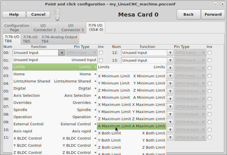
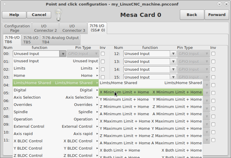
I choused that because there is no separete choice.
But I need separate minimum limit (could be for X Y and Z), maximum limit and separate home for each.
What I need to write in my hal file?
MESA 7i76 also has analog spindle Enable+, Enable-, Dir+, Dir- outputs. Does they support 24V?
Last edit: 28 Feb 2018 13:43 by aleksamc. Reason: Spindle question added.
Please Log in or Create an account to join the conversation.
- andypugh
-

- Offline
- Moderator
-

Less
More
- Posts: 19731
- Thank you received: 4578
28 Feb 2018 13:54 #106699
by andypugh
Replied by andypugh on topic Configuration 7i92m_7i76x1D
There is nothing "magic" about the name "both-home-x", it could be called anything.
If you look elsewhere in the HAL file you will probably find that somewhere there is something like
net both-home-x axis.0.neg-lim-sw-in axis.0.pos-lim-sw-in axis.0.home-sw-in
(May be split over several lines)
To do them separately you cold have:
net red hm2_7i92.0.7i76.0.0.input-07
net blue hm2_7i92.0.7i76.0.0.input-08
net yellow hm2_7i92.0.7i76.0.0.input-09
...
net red axis.0.neg-lim-sw-in
net blue axis.0.pos-lim-sw-in
net yellow axis.0.home-sw-in
Or any variation on that theme.
The following user(s) said Thank You: aleksamc
Please Log in or Create an account to join the conversation.
- Todd Zuercher
-

- Offline
- Platinum Member
-

Less
More
- Posts: 4689
- Thank you received: 1433
28 Feb 2018 14:06 - 28 Feb 2018 14:08 #106703
by Todd Zuercher
Replied by Todd Zuercher on topic Configuration 7i92m_7i76x1D
Last edit: 28 Feb 2018 14:08 by Todd Zuercher.
The following user(s) said Thank You: aleksamc
Please Log in or Create an account to join the conversation.
- aleksamc
-
 Topic Author
- Offline
- Platinum Member
-

Less
More
- Posts: 568
- Thank you received: 67
28 Feb 2018 15:46 #106709
by aleksamc
Replied by aleksamc on topic Configuration 7i92m_7i76x1D
MESA 7i76 also has outputs to control spindle - Enable+, Enable-, Dir+, Dir-. Does they support 24V if I have the same field voltage?
Please Log in or Create an account to join the conversation.
- PCW
-

- Away
- Moderator
-

Less
More
- Posts: 17456
- Thank you received: 5093
28 Feb 2018 16:38 #106715
by PCW
Replied by PCW on topic Configuration 7i92m_7i76x1D
The DIR and ENA outputs are isolated switches (optocoupler outputs) so connect between the + and - leads when ON
They can be to switch 5V to 50V signals with a maximum current of 50 mA. They have no connection to field power
So basically they are used just like a mechanical switch with the limitation that they are DC only, you must observe polarity
and they are limited to switching 50 mA.
You do have to be careful that you do not swicth into a shorted load or you will destroy the optocoupler
The following user(s) said Thank You: aleksamc
Please Log in or Create an account to join the conversation.
- aleksamc
-
 Topic Author
- Offline
- Platinum Member
-

Less
More
- Posts: 568
- Thank you received: 67
09 Mar 2018 14:55 #107152
by aleksamc
Replied by aleksamc on topic Configuration 7i92m_7i76x1D
I start to test pindle analog output and it has some strange behave.
For easy count voltage, I set maximum speed as 1000
Got values of output voltage:
S0 - 0
S10 - 9,64
S50 - 6,37
S100 - 2,37
S200 - 4,78
S300 - 7,92
S400 - 9,69
S500 - 1,64
S600 - 4,03
S700 - 6,45
S800 - 8,9
S900 - 0,9
S1000- 3,28
I've measured voltage between 0V <> Vout.
Output is VERY! unlinear. What is the reason of this?
For easy count voltage, I set maximum speed as 1000
Warning: Spoiler!
Got values of output voltage:
S0 - 0
S10 - 9,64
S50 - 6,37
S100 - 2,37
S200 - 4,78
S300 - 7,92
S400 - 9,69
S500 - 1,64
S600 - 4,03
S700 - 6,45
S800 - 8,9
S900 - 0,9
S1000- 3,28
I've measured voltage between 0V <> Vout.
Output is VERY! unlinear. What is the reason of this?
Please Log in or Create an account to join the conversation.
- PCW
-

- Away
- Moderator
-

Less
More
- Posts: 17456
- Thank you received: 5093
09 Mar 2018 15:05 #107153
by PCW
Replied by PCW on topic Configuration 7i92m_7i76x1D
Are you measuring between TB4 pin 1 and TB4 pin 2? (from SPINDLE- to SPINDLE OUT)
What's the voltage between TB4 pin 1 and TB4 pin 3? (from SPINDLE- to SPINDLE+)
What's the voltage between TB4 pin 1 and TB4 pin 3? (from SPINDLE- to SPINDLE+)
Please Log in or Create an account to join the conversation.
- aleksamc
-
 Topic Author
- Offline
- Platinum Member
-

Less
More
- Posts: 568
- Thank you received: 67
09 Mar 2018 15:28 #107156
by aleksamc
Replied by aleksamc on topic Configuration 7i92m_7i76x1D
Yes, I measure TB4: pin1, Pin2.
Between pin1 and pi3 there is 10,45V.
Between pin1 and pi3 there is 10,45V.
Please Log in or Create an account to join the conversation.
- PCW
-

- Away
- Moderator
-

Less
More
- Posts: 17456
- Thank you received: 5093
09 Mar 2018 15:35 #107157
by PCW
Replied by PCW on topic Configuration 7i92m_7i76x1D
What is the source of the 10.45V, is the 10.45 V constant at all spindle settings?
Please Log in or Create an account to join the conversation.
Moderators: cmorley
Time to create page: 0.214 seconds


