Configuration 7i92m_7i76x1D
- aleksamc
-
 Topic Author
- Offline
- Platinum Member
-

- Posts: 569
- Thank you received: 67
Parameter P097=3 "Neglect inhibition of servo drive" - neglects all limit switches. More over, if it would not be neglected, then err 7 should be displayed, but not. Newer the less, I've connected DI3 and DI4, that corresponds to CCWL and CWL limits to ground (I didn't show it at scheme), meaning set to true, but nothing changed.I have some servo drives where you have to install a jumper to "fake" the limit signal if no limits are to be connected to them.
I will try that tommorow. I don't see any other ways anymore.And I would definitely look into resetting the drives to their default parameter set
Please Log in or Create an account to join the conversation.
- Todd Zuercher
-

- Away
- Platinum Member
-
- Posts: 4764
- Thank you received: 1464
Please Log in or Create an account to join the conversation.
- aleksamc
-
Topic Author
- Offline
- Platinum Member
-
- Posts: 569
- Thank you received: 67
Yes, I'm sure. I see that input is true on interface screen.Are you sure you have the drives enable signals connected right?
I've resettled servo to default but nothing. I suspect that problem in interface of command pulses. May be this one doesn’t supports.
In EP1C manual there are few ways to connect signals to the servodrive.
I use C3-1 differential drive, but may be I need to connect like in C3-2 - single end drive. If somebody know what 7i76 has inner scheme, tell me how to realize such connection.Page 14
Please Log in or Create an account to join the conversation.
- PCW
-

- Offline
- Moderator
-

- Posts: 17994
- Thank you received: 5281
You can also drive single ended inputs with common GND or common 5V connections
Please Log in or Create an account to join the conversation.
- aleksamc
-
Topic Author
- Offline
- Platinum Member
-
- Posts: 569
- Thank you received: 67
Please Log in or Create an account to join the conversation.
- PCW
-
- Offline
- Moderator
-
- Posts: 17994
- Thank you received: 5281
So for single ended with common anode Opto in drive:
7I76 step- to drive step-
7I76 +5 to drive step+
7I76 step+ and GND unconnected
and for single ended common cathode Opto in drive:
7I76 step+ to drive step+
7I76 GND to drive step-
7I76 step- and +5V unconnected
And lastly for differential:
7I76 step+ to drive step+
7I76 step- to drive step-
Please Log in or Create an account to join the conversation.
- aleksamc
-
Topic Author
- Offline
- Platinum Member
-
- Posts: 569
- Thank you received: 67
Could be possible, that I somehow dameged inputs of step/dir signals? For example pluged off singal cable when servos was turned on? I don't remember that I do that, because I try to use them very gently, but for example.
Please Log in or Create an account to join the conversation.
- PCW
-
- Offline
- Moderator
-
- Posts: 17994
- Thank you received: 5281
Since they are opto-isolated, even live connecting them should not be harmful
Please Log in or Create an account to join the conversation.
- aleksamc
-
Topic Author
- Offline
- Platinum Member
-
- Posts: 569
- Thank you received: 67
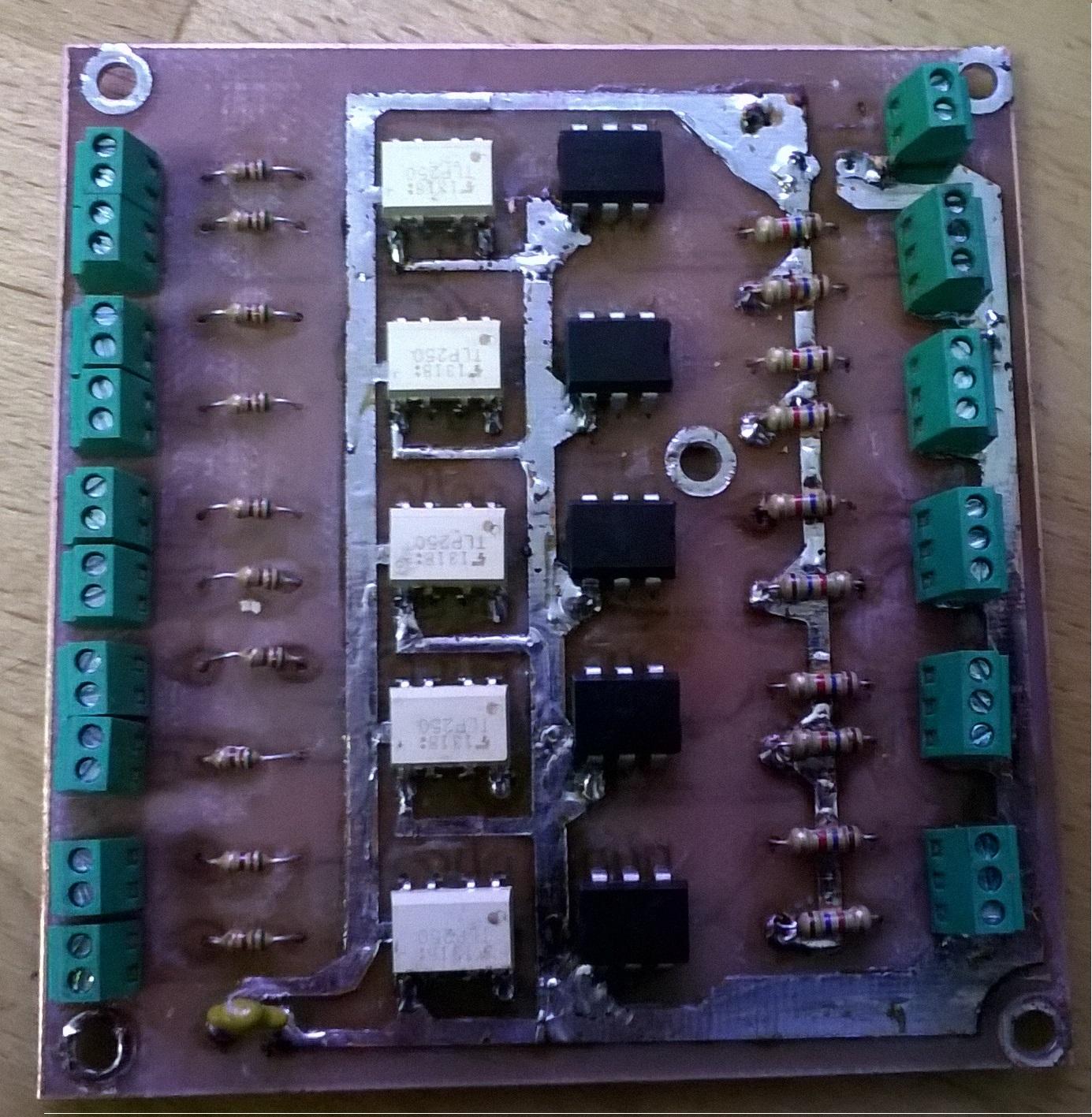
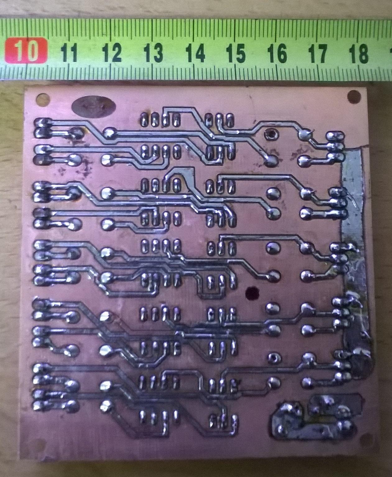
Then I’ve connected to my servo drives 24V encoder throughout resistors 1,5kOhm in single scheme and it worked fine. I see that I need to make some optocoupled PCB board to connect to MESA and use 24V simultaneously. It will solve my problem.
Thank you for your time, Peter, and for your message as Mesa tech specialist. You’ve helped me great.
Please Log in or Create an account to join the conversation.
- aleksamc
-
Topic Author
- Offline
- Platinum Member
-
- Posts: 569
- Thank you received: 67
For step signal I use TLP250 - high freaquencu optocoupler and for Dir signal I use cheap and "slow" 4N27 transistor optocoupler.
I also have problems with only one X axis (port 0). It has big ripple. It's so big that I see that direction changes 7-10 times. I've also connected diode to MESA 7i76 output to check if problem in my pcb or MESA . Ripple goes from MESA side. It seems that problem in PID requlator. But parameters for X, Y and Z are same. I attach also Hal and ini files. Please look them. I think that problem in configuration files.
Please Log in or Create an account to join the conversation.