Allow infinite acceleration/speed on one axis
- Stunning_Rob
-

- Offline
- Junior Member
-

Less
More
- Posts: 21
- Thank you received: 1
19 Jan 2017 16:34 #86164
by Stunning_Rob
Replied by Stunning_Rob on topic Allow infinite acceleration/speed on one axis
Hey andy, thanks for your thoughts.
I did not try M68. As best I am aware the M68 code breaks blending, and Linux will execute the M68 codes as they are received, rather than waiting for the appropriate time (as M67 does). In the case of controlling a laser I suppose this would have the effect of varying the laser intensity as the M68 codes are received and thereby pulsing the laser when it is not at the correct XY position for that engraving point. If the M68 code didn't slow the axis down any (the outcome we want), I expect the laser image would be nigh-illegible due to pulsing the laser at incorrect times, and not give the preferred output.
I did not try M68. As best I am aware the M68 code breaks blending, and Linux will execute the M68 codes as they are received, rather than waiting for the appropriate time (as M67 does). In the case of controlling a laser I suppose this would have the effect of varying the laser intensity as the M68 codes are received and thereby pulsing the laser when it is not at the correct XY position for that engraving point. If the M68 code didn't slow the axis down any (the outcome we want), I expect the laser image would be nigh-illegible due to pulsing the laser at incorrect times, and not give the preferred output.
Please Log in or Create an account to join the conversation.
- tommylight
-

- Offline
- Moderator
-

Less
More
- Posts: 21620
- Thank you received: 7383
19 Jan 2017 17:34 #86173
by tommylight
Replied by tommylight on topic Allow infinite acceleration/speed on one axis
Have a look at this thread, it is the same thing you want, plenty of info.
There is a config attached but it is for quadrature output.
The attached dmap2gcode does a nice job of converting pictures, and it has the setting for not using the Zx or Zy movements, that is essential for what you ( and i ) need.
I modified the dmap2gcode to automatically replace all z values with m67....., so if i did not attach that version, let me know and i will attach it.
Please Log in or Create an account to join the conversation.
- andypugh
-

- Offline
- Moderator
-
Less
More
- Posts: 19861
- Thank you received: 4636
19 Jan 2017 18:12 #86183
by andypugh
That is how the description reads, but I am not sure if that is what happens in practice.
M67 synchronises the change in output with the beginning of the next move. However I don't think that M68 sends all the output values together during the readahead stage. I think it might be worth a trial.
You seem to be saying that M67 breaks blending, if it makes the motion stutter, so M68 can't be much worse.
My own feeling is that G-code for rastering is probably wrong anyway. I think that it would make a lot more sense to have a separate raster generator and intensity mapper.
I did once try writing one, a motion-planner that eats bitmaps rather than G-code, but like so many of my experiments, it died unfinished.
Replied by andypugh on topic Allow infinite acceleration/speed on one axis
In the case of controlling a laser I suppose this would have the effect of varying the laser intensity as the M68 codes are received and thereby pulsing the laser when it is not at the correct XY position for that engraving point. If the M68 code didn't slow the axis down any (the outcome we want), I expect the laser image would be nigh-illegible due to pulsing the laser at incorrect times, and not give the preferred output.
That is how the description reads, but I am not sure if that is what happens in practice.
M67 synchronises the change in output with the beginning of the next move. However I don't think that M68 sends all the output values together during the readahead stage. I think it might be worth a trial.
You seem to be saying that M67 breaks blending, if it makes the motion stutter, so M68 can't be much worse.
My own feeling is that G-code for rastering is probably wrong anyway. I think that it would make a lot more sense to have a separate raster generator and intensity mapper.
I did once try writing one, a motion-planner that eats bitmaps rather than G-code, but like so many of my experiments, it died unfinished.
The following user(s) said Thank You: Stunning_Rob
Please Log in or Create an account to join the conversation.
- Todd Zuercher
-

- Away
- Platinum Member
-

Less
More
- Posts: 4742
- Thank you received: 1455
19 Jan 2017 18:15 - 19 Jan 2017 18:28 #86184
by Todd Zuercher
Replied by Todd Zuercher on topic Allow infinite acceleration/speed on one axis
I believe that your problem with trying to use XYA is that The new trajectory planner only works with XYZ, and adding A into the mix reverts the system back to the old 1 line look-ahead acceleration limit.
I just did a little experimenting with M67 in a simulation and it works fine if... and this is a BIG IF. The distance between the changes of M67 settings has to be long enough to take more than 1 servo-period to execute at the commanded speed.
In one of the generic axis sims included with Linuxcnc.
This code works
And this does not
I just did a little experimenting with M67 in a simulation and it works fine if... and this is a BIG IF. The distance between the changes of M67 settings has to be long enough to take more than 1 servo-period to execute at the commanded speed.
In one of the generic axis sims included with Linuxcnc.
This code works
%
G20
G92.1
G64 P0.05 Q.1
S18000 M3G54
G90
F300

G64
G0 X0 Y0
G1 X1
 M67E0Q100
G1 X1.1
 M67E0Q0
G1 X1.2
 M67E0Q100
G1 X1.21
 M67E0Q0
G1 X1.22
 M67E0Q100
G1 X1.24
 M67E0Q0
G1 X1.25
 M67E0Q100
G1 X1.29
 M67E0Q0
G1 X1.30
 M67E0Q100
G1 X1.35
 M67E0Q0
G1 X1.45
 M67E0Q100
G1 X1.5
 M67E0Q0
G1 X1.505
 M67E0Q100
G1 X2
 M67E0Q0
G1 X3
G1 Y1
G1 X2
 M67E0Q100
G1 X1
 M67E0Q0
G1 X0

G53 Z0
G92.1
%
And this does not
%
G20
G92.1
G64 P0.05 Q.1
S18000 M3G54
G90
F300

G64
G0 X0 Y0
G1 X1
 M67E0Q100
G1 X1.1
 M67E0Q0
G1 X1.2
 M67E0Q100
G1 X1.21
 M67E0Q0
G1 X1.22
 M67E0Q100
G1 X1.24
 M67E0Q0
G1 X1.25
 M67E0Q100
G1 X1.29
 M67E0Q0
G1 X1.300
 M67E0Q100
G1 X1.301 (this is the offending line of code that breaks it all)
 M67E0Q0
G1 X1.45
 M67E0Q100
G1 X1.5
 M67E0Q0
G1 X1.505
 M67E0Q100
G1 X2
 M67E0Q0
G1 X3
G1 Y1
G1 X2
 M67E0Q100
G1 X1
 M67E0Q0
G1 X0

G53 Z0
G92.1
%
Last edit: 19 Jan 2017 18:28 by Todd Zuercher.
Please Log in or Create an account to join the conversation.
- Todd Zuercher
-
- Away
- Platinum Member
-
Less
More
- Posts: 4742
- Thank you received: 1455
19 Jan 2017 18:24 - 19 Jan 2017 18:25 #86185
by Todd Zuercher
Replied by Todd Zuercher on topic Allow infinite acceleration/speed on one axis
Here is a Halscope of the above two codes.
Screen shot of the good code
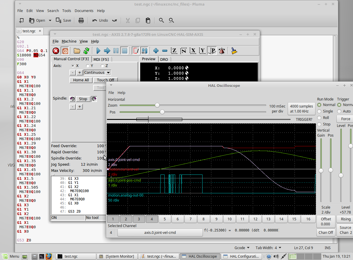
And the bad.
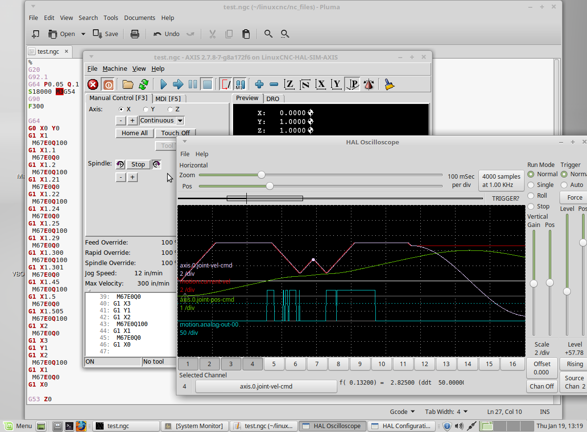
Screen shot of the good code
And the bad.
Last edit: 19 Jan 2017 18:25 by Todd Zuercher.
Please Log in or Create an account to join the conversation.
- Todd Zuercher
-
- Away
- Platinum Member
-
Less
More
- Posts: 4742
- Thank you received: 1455
19 Jan 2017 18:32 #86186
by Todd Zuercher
Replied by Todd Zuercher on topic Allow infinite acceleration/speed on one axis
So in my above simulation the maximum resolution for your raster at 300ipm scan rate would be 0.005 inches. (and that might be pushing your luck, double that would probably be safer.)
The following user(s) said Thank You: Stunning_Rob
Please Log in or Create an account to join the conversation.
- tommylight
-
- Offline
- Moderator
-
Less
More
- Posts: 21620
- Thank you received: 7383
19 Jan 2017 18:58 #86187
by tommylight
Replied by tommylight on topic Allow infinite acceleration/speed on one axis
One more thing regarding this, the G0 speed must be the same as the G1, so i just replace all G0 with G1 and it moves smoothly. Again this is for my case that is same as for lasers, i just use a PWM controlled pressure on the spindle head.
Please Log in or Create an account to join the conversation.
- Stunning_Rob
-
- Offline
- Junior Member
-
Less
More
- Posts: 21
- Thank you received: 1
19 Jan 2017 20:43 #86195
by Stunning_Rob
Replied by Stunning_Rob on topic Allow infinite acceleration/speed on one axis
Thanks to all for your thoughts,
Tommy -> If you can post the link and attachments that you mentioned in your post I would like to see how they look. I don't fully understand what you mean, but probably with your links and attachments I will be able to. It sounds like you have this solved, so I would like to take a look.
Andy -> I will test the use of M68 and revert back with results so we know for sure how it will act under these circumstances.
Todd -> Your response has given me some things to check:
1.) Based on servo period and image resolution (in this case, the minimum distance between M67 changes) we should be able to find the maximum speed at which any given image could be engraved via M67.
2.) Thanks for the heads up on XYZA vs XYZ in the trajectory planner. I'll create some temp config settings and instead of XYZA, I'll run XYZ with Z controlling the laser (and no 'traditional Z axis' just for testing) to how this effects my results.
I will revert back regarding the above after some trial runs.
Please Log in or Create an account to join the conversation.
- tommylight
-
- Offline
- Moderator
-
Less
More
- Posts: 21620
- Thank you received: 7383
19 Jan 2017 20:53 #86197
by tommylight
Replied by tommylight on topic Allow infinite acceleration/speed on one axis
Here it is, but the hal file will not work for you as it uses quadrature output for driving l298 IC's.
You can use the PWM part from it and paste it in your hal file.
Dang can not attach from the tablet, will do as soon as i get to my laptop.
You can use the PWM part from it and paste it in your hal file.
Dang can not attach from the tablet, will do as soon as i get to my laptop.
The following user(s) said Thank You: Stunning_Rob
Please Log in or Create an account to join the conversation.
- Stunning_Rob
-
- Offline
- Junior Member
-
Less
More
- Posts: 21
- Thank you received: 1
20 Jan 2017 15:00 - 20 Jan 2017 15:03 #86252
by Stunning_Rob
Replied by Stunning_Rob on topic Allow infinite acceleration/speed on one axis
All,
Based on your recommendations yesterday I ran some tests last night. I need more time to test the further this weekend, but wanted to present my findings now to get your input on what's happening.
I am leaning heavily on Todd's statement of:
"I just did a little experimenting with M67 in a simulation and it works fine if... and this is a BIG IF. The distance between the changes of M67 settings has to be long enough to take more than 1 servo-period to execute at the commanded speed."
So I ran test files, while increasing the distance between M67 changes as follows:
Test #1:
A.) M67 command spacing set at 0.15mm
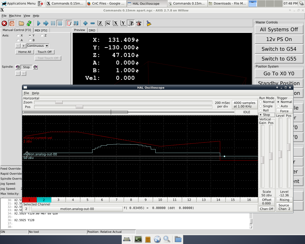
This output is the same as I have been testing in my previous posts, and shows the velocity reduction I experienced while trying M67 commands. It looks much as expected based on my history with the issue. Note: I don't often use halscope, so I'm not so good with it. The only way I was able to see the graphs move was to use the run mode "Roll" and then manually click "Stop". I tried to stop the graphs in roughly the same place each run to get consistent results.
B.) M67 command spacing set at 0.30mm
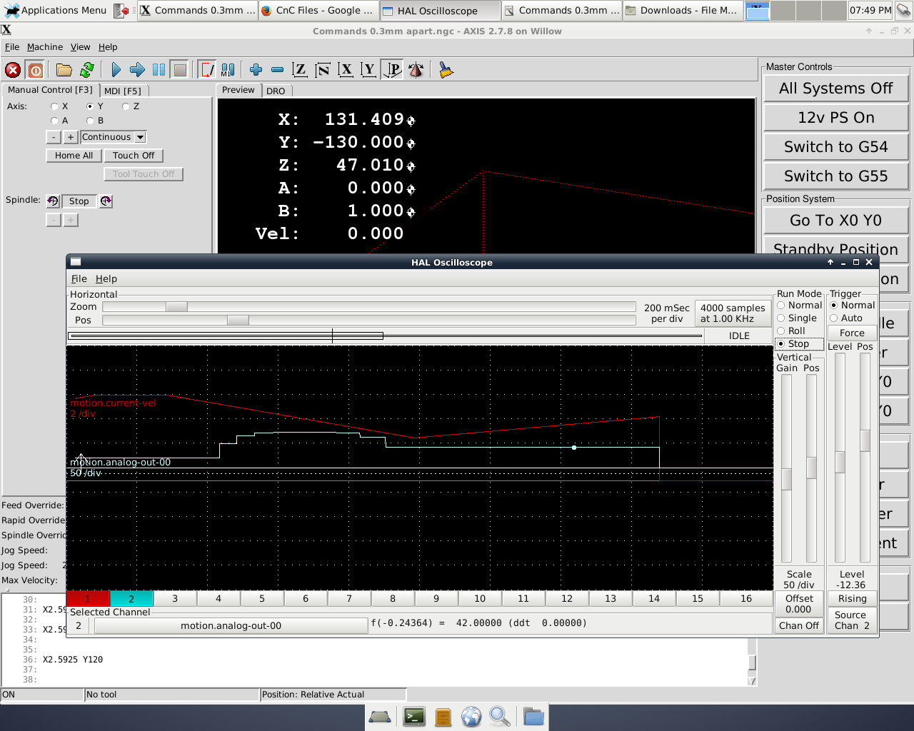
More or less the same as 0.15mm spacing...
C.) 0.6mm spacing

D.) 1.2mm spacing
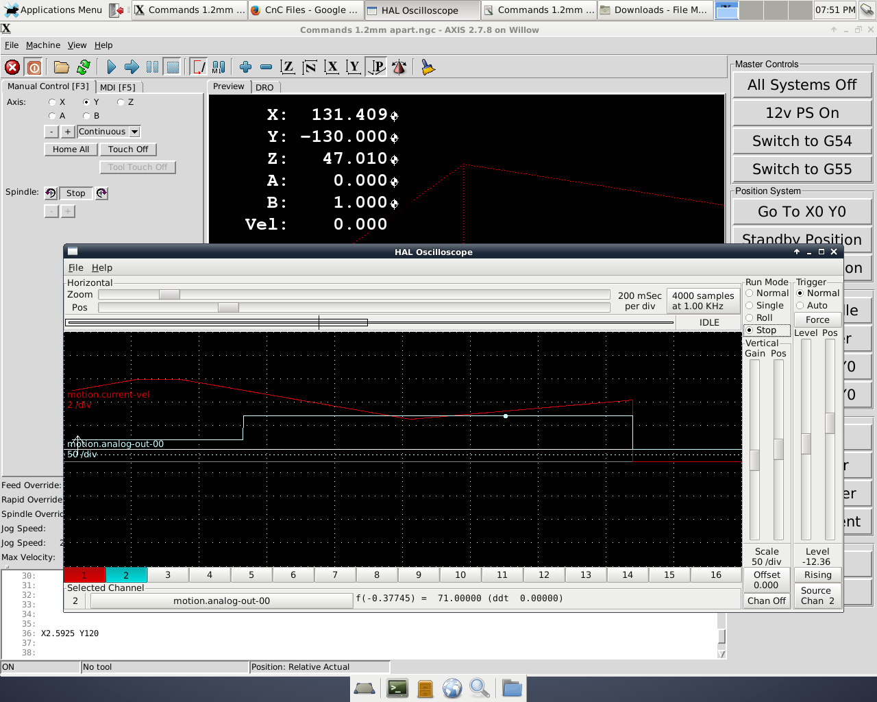
So at this point I stop and evaluate the data (images) to see if anything makes sense. I see that in each case my velocity starts dropping before any M67 commands occur, i.e. the red line begins sloping down before the blue line goes up. I don't really know what that means, although I can take a few guesses which are likely all incorrect (Linux is expecting to have to slow down to issue M67 command so it starts slowing down before the command, etc).
Its possible that the I have not yet spaced my commands far enough apart to get outside of the "1 servo period" distance. I have never had reason to tweak my servo period, so perhaps its set extremely high and is causing my results. In the previous tests I was running at a feed rate of 420mm/min. If I make an educated guess as to the highest allowable servo period for 1.2mm M67 spacing I get (420mm/min = 1.2mm in ~ 0.17 sec) 0.17 sec = 1.7 x10^8 ns. My .ini file shows:
[EMCMOT]
EMCMOT = motmod
COMM_TIMEOUT = 1.0
COMM_WAIT = 0.010
BASE_PERIOD = 100000
SERVO_PERIOD = 1000000
and I think those values are in nanoseconds, meaning my servo period is 1.0 x10^6 ns. Perhaps I am wrong or confused in these numbers somehow, but if they are correct I should be able to attain a ( 420mm/min ~ 0.007mm in 1 nanosecond) 0.007mm spacing on M67 commands (note that I am testing a speed much lower than your 300in/min so it makes sense that I could hold smaller spacing then you are able to, so at least this seems accurate). Unfortunately I don't seem to be able to hold these spacing values, so perhaps something else is amiss here? Any thoughts on the above are welcome.
Test #2:
So at this point I wanted a break, so I decided to investigate the use of M68 vs M67, and received the following graph:
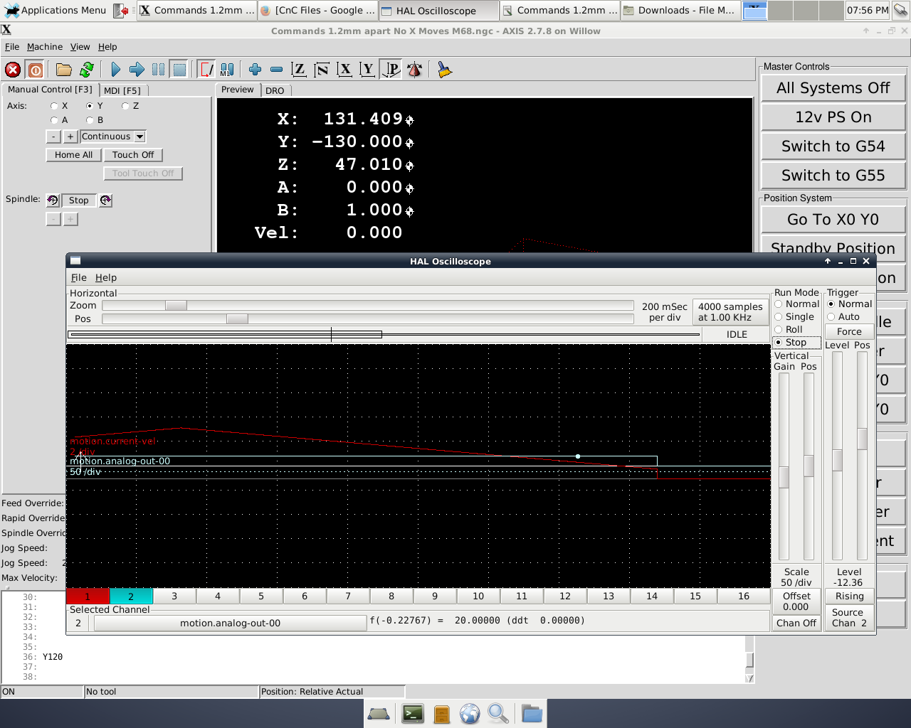
This yielded (what is now the new) worst results I have gotten in any testing. The velocity was abysmal, staying mostly near 100mm/min and often dropping near zero and never really getting close to 420mm/min as the M67 testing would always hit prior to issuing M67 commands. This leads me to think it is issuing the M68 commands as received, and that (at least in this case) M68 is directly affecting axis velocity in a big way.
I did not do further testing with M68 because the axis never got to 420mm/min at any point during my initial test.
Test #3:
I still have on my list to do a check of XYZA system as a simple three axis system using one of the 'normal' axes to control the laser via step pulses, to see if it increases performance since it was pointed out that XYZA will fall back to one line look ahead.
I attached some of the g-code/config files I used for the tests if someone has time to look at them and offer any guidance or tips for improvement based on them.
Based on your recommendations yesterday I ran some tests last night. I need more time to test the further this weekend, but wanted to present my findings now to get your input on what's happening.
I am leaning heavily on Todd's statement of:
"I just did a little experimenting with M67 in a simulation and it works fine if... and this is a BIG IF. The distance between the changes of M67 settings has to be long enough to take more than 1 servo-period to execute at the commanded speed."
So I ran test files, while increasing the distance between M67 changes as follows:
Test #1:
A.) M67 command spacing set at 0.15mm
This output is the same as I have been testing in my previous posts, and shows the velocity reduction I experienced while trying M67 commands. It looks much as expected based on my history with the issue. Note: I don't often use halscope, so I'm not so good with it. The only way I was able to see the graphs move was to use the run mode "Roll" and then manually click "Stop". I tried to stop the graphs in roughly the same place each run to get consistent results.
B.) M67 command spacing set at 0.30mm
More or less the same as 0.15mm spacing...
C.) 0.6mm spacing
D.) 1.2mm spacing
So at this point I stop and evaluate the data (images) to see if anything makes sense. I see that in each case my velocity starts dropping before any M67 commands occur, i.e. the red line begins sloping down before the blue line goes up. I don't really know what that means, although I can take a few guesses which are likely all incorrect (Linux is expecting to have to slow down to issue M67 command so it starts slowing down before the command, etc).
Its possible that the I have not yet spaced my commands far enough apart to get outside of the "1 servo period" distance. I have never had reason to tweak my servo period, so perhaps its set extremely high and is causing my results. In the previous tests I was running at a feed rate of 420mm/min. If I make an educated guess as to the highest allowable servo period for 1.2mm M67 spacing I get (420mm/min = 1.2mm in ~ 0.17 sec) 0.17 sec = 1.7 x10^8 ns. My .ini file shows:
[EMCMOT]
EMCMOT = motmod
COMM_TIMEOUT = 1.0
COMM_WAIT = 0.010
BASE_PERIOD = 100000
SERVO_PERIOD = 1000000
and I think those values are in nanoseconds, meaning my servo period is 1.0 x10^6 ns. Perhaps I am wrong or confused in these numbers somehow, but if they are correct I should be able to attain a ( 420mm/min ~ 0.007mm in 1 nanosecond) 0.007mm spacing on M67 commands (note that I am testing a speed much lower than your 300in/min so it makes sense that I could hold smaller spacing then you are able to, so at least this seems accurate). Unfortunately I don't seem to be able to hold these spacing values, so perhaps something else is amiss here? Any thoughts on the above are welcome.
Test #2:
So at this point I wanted a break, so I decided to investigate the use of M68 vs M67, and received the following graph:
This yielded (what is now the new) worst results I have gotten in any testing. The velocity was abysmal, staying mostly near 100mm/min and often dropping near zero and never really getting close to 420mm/min as the M67 testing would always hit prior to issuing M67 commands. This leads me to think it is issuing the M68 commands as received, and that (at least in this case) M68 is directly affecting axis velocity in a big way.
I did not do further testing with M68 because the axis never got to 420mm/min at any point during my initial test.
Test #3:
I still have on my list to do a check of XYZA system as a simple three axis system using one of the 'normal' axes to control the laser via step pulses, to see if it increases performance since it was pointed out that XYZA will fall back to one line look ahead.
I attached some of the g-code/config files I used for the tests if someone has time to look at them and offer any guidance or tips for improvement based on them.
Last edit: 20 Jan 2017 15:03 by Stunning_Rob. Reason: Correcting attachments
Please Log in or Create an account to join the conversation.
Time to create page: 0.335 seconds