Allow infinite acceleration/speed on one axis
- Stunning_Rob
-

- Offline
- Junior Member
-

Less
More
- Posts: 21
- Thank you received: 1
20 Jan 2017 22:45 #86304
by Stunning_Rob
Replied by Stunning_Rob on topic Allow infinite acceleration/speed on one axis
Tommy,
Wow, your file is brutal. Haven't seen my average velocity that low in a long time. Like yikes, I might have got up to 50mm/min once or twice near the shirt/shoulders on the top right,and then not up to speed (420mm/min) until the long straight away.
The photo doesn't do justice to how bad the velocities were. It looks like it went all the way down to v=0 at one point -> ouch!
Gonna test a few more things, kick my velo and accel up and see if I can replicate the graph that Todd got before, to see if its related to velo and acceleration.
Please Log in or Create an account to join the conversation.
- tommylight
-

- Away
- Moderator
-

Less
More
- Posts: 21260
- Thank you received: 7255
20 Jan 2017 23:05 #86310
by tommylight
Replied by tommylight on topic Allow infinite acceleration/speed on one axis
Oh well, you do have acceleration problems, as Tod mentioned, you should have changed that but you can leave velocity as is.
I have acceleration set at 5000 or 2000 depending on the machine, and that file runs fine up to 3000mm/minute.
I did test that file, they are my grandfather and grandmother on fathers side, came out really nice.
I have acceleration set at 5000 or 2000 depending on the machine, and that file runs fine up to 3000mm/minute.
I did test that file, they are my grandfather and grandmother on fathers side, came out really nice.
Please Log in or Create an account to join the conversation.
- Stunning_Rob
-

- Offline
- Junior Member
-

Less
More
- Posts: 21
- Thank you received: 1
20 Jan 2017 23:51 #86318
by Stunning_Rob
Replied by Stunning_Rob on topic Allow infinite acceleration/speed on one axis
Ok, so with the following axis settings:
MAX_VELOCITY = 1500.0
MAX_ACCELERATION = 100000.0
STEPGEN_MAXACCEL = 125000.0
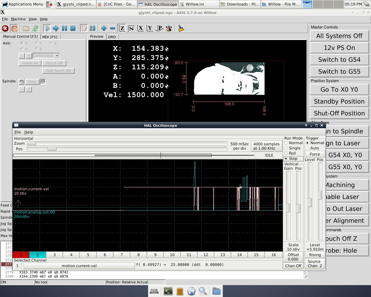
The file runs fine. Velocity stays pegged at 1500mm/min for the length of the image, with a graph as follows:
I guess this is good and bad news.
Good news in that increasing the acceleration fixes the lag problem that I was having, and makes sense with what we decided was the reason that Todd could get the file to work while I was having difficulty.
Bad news in that this means that M67 wants to drop velocity to zero (not sure why...boo) although nothing is really happening with the axis. Since I don't want to push the acceleration values of my axis just to account for this, I will investigate the next possibility.
I will spend some time investigating running the image as XYZA, except temporarily throw out Z, and run Z as my A (controlling laser via step pulses). With some ideas gained in testing the M67 command I have some ideas on maybe how this might work.
Please Log in or Create an account to join the conversation.
- tommylight
-

- Away
- Moderator
-

Less
More
- Posts: 21260
- Thank you received: 7255
21 Jan 2017 00:14 #86320
by tommylight
Replied by tommylight on topic Allow infinite acceleration/speed on one axis
My grandfather got to be famous on the net !!!!! LOL 


I never knew him, he died long before i was born, and i was born long before ............well anything, i am to darn old !
I never knew him, he died long before i was born, and i was born long before ............well anything, i am to darn old !
Please Log in or Create an account to join the conversation.
- Todd Zuercher
-

- Away
- Platinum Member
-

Less
More
- Posts: 4696
- Thank you received: 1439
21 Jan 2017 03:13 #86332
by Todd Zuercher
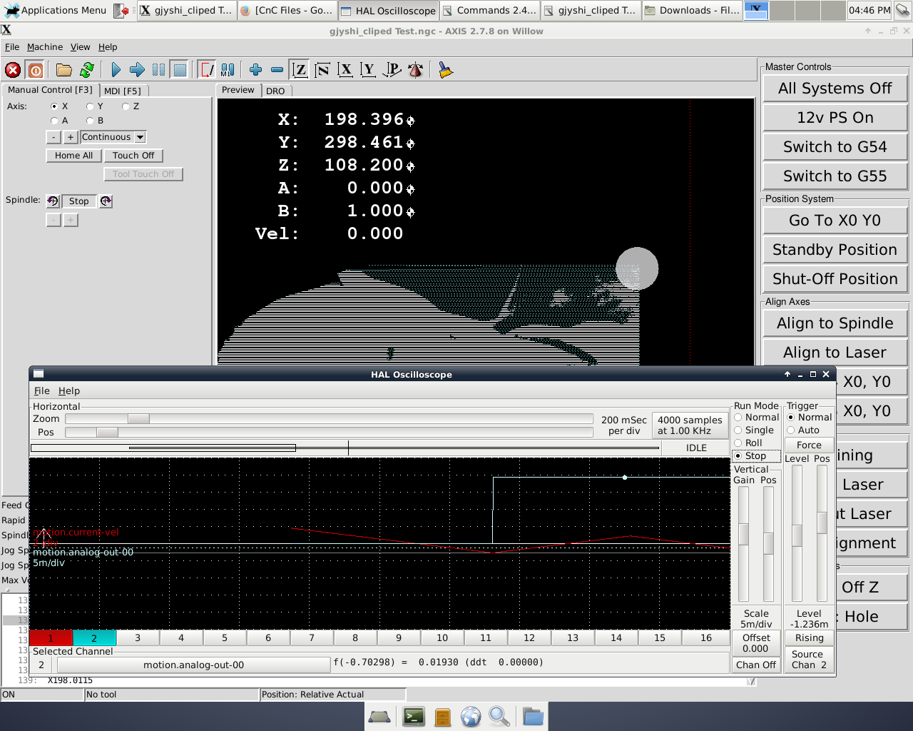
In the Halscope plot I posted, the first move of the file is moving from where the file ended (from previous run). That is the first long velocity move, then the axis reverses direction, resulting in the deceleration to 0 (the point in the middle). Finally the move(s) with the M67 codes, were all made without any change in velocity.
I don't know what is up with the deceleration your seeing. (I haven't taken the time to look at the code Tommy posted.)
What sort of arrangement do your have for your X-axis bearings your having trouble with. Maybe we could suggest a simple improvement. I maintain a machine at work with a seriously overloaded axis and it eats bearings as well.
Replied by Todd Zuercher on topic Allow infinite acceleration/speed on one axis
Todd,
I'm just a small time hobby machinist making things out of wood for friends and family. I used to run faster ('faster' for me anyway....maybe 1,500mm/min and increased accelerations to match) but I kept ruining bearings on my X axis. I chalked this up to the weight of the Z-Axis riding on the X-axis rails, and that the larger forces imposed by the increased acceleration were probably causing 'some' amount of damage. How much I'm not sure, but I can run my little machine about a year between bearing changes when using a max around 420mm/min but I start getting (what I call) "bearing drag" after about 2 months at the higher speeds. The plastic at the ends of the bearings starts tearing apart, so that when moving in one direction the bits of plastic would ride up into the bearing, then when moving the other direction the axis had to overcome the force to get past it and the axis would 'jump' about 1mm resulting in all kinds of horrible looking things any time the axis reversed direction. Long story short, for my poor man's machining budget it doesn't bother me if it takes 10x as long to finish something, my machine utilization rate is probably about 5% over the course of a year anyway. But not to worry -> I'm saving up my pennies for one of these fancy metal milling machines with those (crazy!) velocity rates. I will be there one day...
Anyway, back to our discussion:
Will it tell you what the velocity is dropping to when it executes that 2nd y-move code (with Q20)? I see a sharp point there where it looks like velocity drops considerably and then shoots back up. Based on the rest of the graph that looks like the v=0 point. If that is actually what's happening in your simulator then that would be somewhat similar to how mine keeps dropping off somewhat near the same point.
If I was good with halscope we could probably figure out if they were dropping off at precisely the same time. The remainder of the difference in your velocity graph and mine could then be summed up in acceleration rates most likely. My graph takes the long slow journey towards velocity = 0 because my acceleration values are so low. In your simulated mode your accel values are probably >>> greater than mine, hence the reason yours can drop to zero and recover within such a short time.
It could be my eyes playing tricks on me, but your graph appears to follow the same acceleration rate (linear velocity increase) during "movement start" and the quick (what I am calling) v=0 point of your graph, although the deceleration rate at the v=0 point is not the same as your ending deceleration rate; potentially interesting but for another discussion.
In the Halscope plot I posted, the first move of the file is moving from where the file ended (from previous run). That is the first long velocity move, then the axis reverses direction, resulting in the deceleration to 0 (the point in the middle). Finally the move(s) with the M67 codes, were all made without any change in velocity.
I don't know what is up with the deceleration your seeing. (I haven't taken the time to look at the code Tommy posted.)
What sort of arrangement do your have for your X-axis bearings your having trouble with. Maybe we could suggest a simple improvement. I maintain a machine at work with a seriously overloaded axis and it eats bearings as well.
Please Log in or Create an account to join the conversation.
- Stunning_Rob
-

- Offline
- Junior Member
-

Less
More
- Posts: 21
- Thank you received: 1
21 Jan 2017 05:42 #86343
by Stunning_Rob
Replied by Stunning_Rob on topic Allow infinite acceleration/speed on one axis
Todd,
Thanks for pointing that out, I was overlooking the obvious (duh!) that your axis had to first position itself, come to a stop, then execute the file. Makes perfect sense now once looking at the graph and file.
So I revisited my good M67 buddy and have the following thoughts:
1.) Acceleration is not a factor
2.) Velocity is not a factor
Based on those two, for now I am ruling out modifications to the .ini file, as the servo thread and axis values 'should be' fine
So I looked at the .hal files, and what I could do to improve. So far all I have found to help is moving the analog motion code block:
loadrt pwmgen output_type=0
addf pwmgen.update servo-thread
addf pwmgen.make-pulses base-thread
setp pwmgen.0.enable TRUE
net laser-pwm-generator motion.analog-out-00 => pwmgen.0.value
net linux-to-laser-driver-board-signal-00 pwmgen.0.pwm => parport.0.pin-03-out
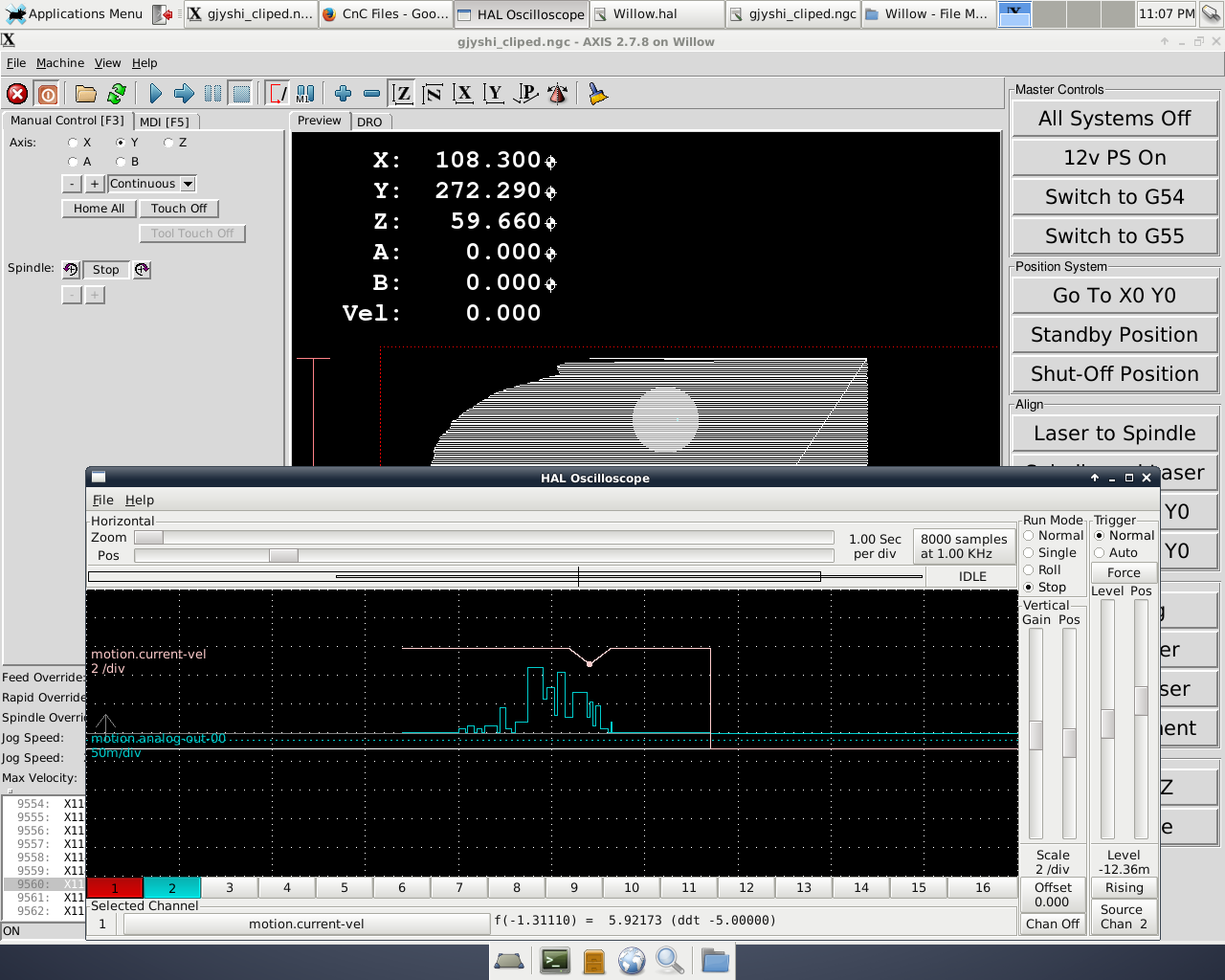
from custom.hal to willow.hal (mymachinename.hal -> the first hal loaded (as best I'm aware anyway), before custom.hal and before custom_postgui.hal). This improves performance and I am at the following graph now:
This is better than I was getting before, with velocity dropping to 5.9mm/sec (vs 7mm/s max, or ~15% drop). The drops are far less frequent then they were before, and velocity is not dropping anywhere near 0 as it previously was. Can't explain that yet, maybe the order of loading hal components matters? Not sure on why the sudden improvement....still pondering that. Also, I can't explain that temporary drop in velocity, but its a lot better than it use to be for what that's worth.
In looking at the hal and ini files I noticed that I'm still loading the A-Axis from when I was testing with it, so I will remove it to ensure its not unnecessarily hogging resources as well.
This is better progress then I've made recently, so thanks to all for the help so far.
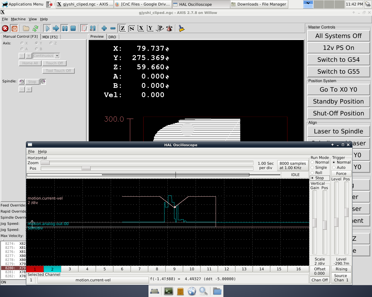
I had a test file running while making this post, and notice a bit bigger drop.
This one was down to ~4.5mm/s, or 35% drop (close to the 40% velocity loss I was experiencing before). So for sure some problem remains, but its not dropping to 40% velo near as often as it was before, for what that's worth.
I will work on this more this weekend and report back.
Please Log in or Create an account to join the conversation.
- Stunning_Rob
-

- Offline
- Junior Member
-

Less
More
- Posts: 21
- Thank you received: 1
21 Jan 2017 05:48 - 21 Jan 2017 05:51 #86344
by Stunning_Rob
Replied by Stunning_Rob on topic Allow infinite acceleration/speed on one axis
You can see a few pics of my setup here:
www.instructables.com/id/Add-Laser-Etchi...ities-to-a-CnC-Mill/
I wrote about adding the laser so I could mill and engrave within the same coordinate system. It is working really well for vector engravings so I recently started trying to engrave images and that's where I'm at now.
The 3d printed housing really doesn't add that much weight to the Z-axis since the majority of it is 8mm HDPE plastic, so I don't think my adding the laser + housing made my bearing issue much worse. It was destroying bearings at about the same rate before I added the laser (once per year or so), but only since trying to raster engrave did I kick up the velocity to around 1500mm/min and that's when the bearing went bad after about 2 months of that, so I dialed it way back down.
Anyways I can beat all the cool kids and their laser cutters since they cry when material gets over 5-8mm thick but I laser etch whatever I want then mill through any piece of wood I can fit under my Z-axis (about 30mm).
Last edit: 21 Jan 2017 05:51 by Stunning_Rob. Reason: Edited for clarity.
Please Log in or Create an account to join the conversation.
- andypugh
-

- Offline
- Moderator
-

Less
More
- Posts: 19797
- Thank you received: 4606
21 Jan 2017 11:18 #86347
by andypugh
The order that components are loaded is not important, but the order that they are added to the servo thread matters.
You should read inputs, then do calculations, then write outputs.
You can actually add a number to the end of an "addf" command to force a position in the thread sequence. positive numbers from the top, negative numbers from the bottom.
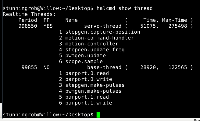
With Linuxcnc running you can run the command "halcmd show thread" in a terminal to get a list of the functions and the order they are executing. Make sure that they are in the read-process-write ordering.
Replied by andypugh on topic Allow infinite acceleration/speed on one axis
Can't explain that yet, maybe the order of loading hal components matters?
The order that components are loaded is not important, but the order that they are added to the servo thread matters.
You should read inputs, then do calculations, then write outputs.
You can actually add a number to the end of an "addf" command to force a position in the thread sequence. positive numbers from the top, negative numbers from the bottom.
With Linuxcnc running you can run the command "halcmd show thread" in a terminal to get a list of the functions and the order they are executing. Make sure that they are in the read-process-write ordering.
Please Log in or Create an account to join the conversation.
- Stunning_Rob
-

- Offline
- Junior Member
-

Less
More
- Posts: 21
- Thank you received: 1
21 Jan 2017 17:07 #86375
by Stunning_Rob
Replied by Stunning_Rob on topic Allow infinite acceleration/speed on one axis
Andy,
Thanks for the heads up about the loading order. I've never adjusted it before. Here's what I have now:
For the servo thread I'm not sure if anything there needs to be reordered?
For the base thread, should I reorder it to load as follows:
parport.0.read
parport.1.read
stepgen.make-pulses
pwmgen.make-pulses
parport.1.write
parport.2.write
Its not much of an adjustment, but perhaps it matters as you've pointed out.
Note: I see that my servo thread 'max time' is less than my servo thread period, while the same is not true for the base thread (122k vs 100k). Perhaps this is potentially where the random flutter I am getting on M67 commands is coming from? I've never adjusted or worried much about these values as the machine has worked well for cnc and vector engraving, but maybe now that I'm doing raster the max-time in the base thread is causing me some problems?
Please Log in or Create an account to join the conversation.
- andypugh
-

- Offline
- Moderator
-

Less
More
- Posts: 19797
- Thank you received: 4606
21 Jan 2017 17:47 #86378
by andypugh
Replied by andypugh on topic Allow infinite acceleration/speed on one axis
You might be able to move parport.read to the servo thread if you are not reading encoders.
The following user(s) said Thank You: Stunning_Rob
Please Log in or Create an account to join the conversation.
Time to create page: 0.236 seconds

