Rotary table configuration
- Sparky961
-
 Topic Author
- Offline
- Elite Member
-

Less
More
- Posts: 210
- Thank you received: 15
08 Mar 2016 01:18 #71197
by Sparky961
Rotary table configuration was created by Sparky961
While waiting for various components to arrive I've turned my attention to testing using a rotary table with attached servo. It provides a load to tune and has no hard limits to be concerned with. That's where the easy part ends.
I'm attaching my full INI, and applicable HAL files in the hopes that someone can point out what I've done that's silly.
As I've mentioned in previous threads, the servos I'm working with give 4000 counts per revolution in 4X quadrature mode. This one is connected to the rotary table input via a spring coupling, so effectively 1:1 but with some room for misalignment. For every revolution the table rotates 4 degrees.
Doing the math myself, which is admittedly not my strong suit, I get a 90:1 reduction rate and figure my encoder scale should be a simple 1000.
I can get the table to rotate but can't make much sense out of the numbers I'm seeing in the AXIS GUI. For example, starting up LinuxCNC fresh I begin with the following:
hm2_5i25.0.encoder.03.count: 0
axis.3.joint-pos-fb: 0
I then execute "G91 G01 A10 F50' using MDI and these change to:
hm2_5i25.0.encoder.03.count: 1349599
axis.3.joint-pos-fb: 1349.599
So at least the two agree with each other, and also the encoder scale value that's set. **BUT** is my understanding that the G-code should have rotated the axis incrementally by 10 degrees not correct?
Executing the above G-code once more, I end up with:
hm2_5i25.0.encoder.03.count: 2691195
axis.3.joint-pos-fb: 2691.195
Dividing this new position by 2 gives (in counts) 1345597.5 - which is double the original plus one full rotation of the input.
I have to conclude that my scaling values are wrong but I've been over the docs and can't figure what I've misunderstood. Does something work differently for angular/rotational axes?
Possibly related to this is my lack of understanding of OUTPUT_SCALE. Should this be "1" if you're not doing anything fancy, or should it be the maximum scale of the analog output (eg. 10 [V])?
Much thanks...
Please Log in or Create an account to join the conversation.
- Sparky961
-
Topic Author
- Offline
- Elite Member
-
Less
More
- Posts: 210
- Thank you received: 15
08 Mar 2016 11:12 #71209
by Sparky961
Replied by Sparky961 on topic Rotary table configuration
It would appear that my above troubles are PID tuning related. There was no logic to the numbers I was getting so I went back to a bare servo. I got the counts and degree scaling right (yes, 1000 - has to be) but lots of oscillation still. I knew tuning would be difficult but I figured getting it reasonably close would be easy, then the fine tuning more difficult.
Please Log in or Create an account to join the conversation.
- andypugh
-

- Offline
- Moderator
-

Less
More
- Posts: 19876
- Thank you received: 4642
08 Mar 2016 14:48 #71225
by andypugh
How far did the table actually move?
Replied by andypugh on topic Rotary table configuration
I then execute "G91 G01 A10 F50' using MDI and these change to:
hm2_5i25.0.encoder.03.count: 1349599
axis.3.joint-pos-fb: 1349.599
How far did the table actually move?
Please Log in or Create an account to join the conversation.
- Sparky961
-
Topic Author
- Offline
- Elite Member
-
Less
More
- Posts: 210
- Thank you received: 15
09 Mar 2016 04:09 #71255
by Sparky961
I didn't record it because it was moving way more (factor of 10 or more) than it should have, but not the same factor for different amounts of commanded movement. I quickly came to the conclusion that trying to make sense of the numbers wasn't useful.
I'll follow this up with my PID tuning attempts and hopefully I can get something stable going on the rotary axis. When I do that, what information would be most useful to post here so you can see what's happening and offer suggestions?
Replied by Sparky961 on topic Rotary table configuration
How far did the table actually move?
I didn't record it because it was moving way more (factor of 10 or more) than it should have, but not the same factor for different amounts of commanded movement. I quickly came to the conclusion that trying to make sense of the numbers wasn't useful.
I'll follow this up with my PID tuning attempts and hopefully I can get something stable going on the rotary axis. When I do that, what information would be most useful to post here so you can see what's happening and offer suggestions?
Please Log in or Create an account to join the conversation.
- andypugh
-
- Offline
- Moderator
-
Less
More
- Posts: 19876
- Thank you received: 4642
09 Mar 2016 13:37 #71271
by andypugh
Replied by andypugh on topic Rotary table configuration
Put a halmeter on the pid.N.error pin. If it increases rather than decreases then it is likely that the encoder scale or output scale need to be inverted.
Start with a Pgain of 0.0001 and keep moving the decimal point until the table starts to move.
Start with a Pgain of 0.0001 and keep moving the decimal point until the table starts to move.
Please Log in or Create an account to join the conversation.
- Sparky961
-
Topic Author
- Offline
- Elite Member
-
Less
More
- Posts: 210
- Thank you received: 15
10 Mar 2016 03:18 - 10 Mar 2016 22:33 #71304
by Sparky961
Replied by Sparky961 on topic Rotary table configuration
Ok, I'll try to detail this pretty thoroughly so that any assumptions I'm making are obvious.
Prolog: I'm using Advanced Motion Controls B12A6D servo amps. Prior to beginning the tuning below, I've turned the Loop Gain all the way down (manual says this is for velocity mode and should be full CCW for current mode). Current limit is set to max - my logic being I want it to really push the motors hard when called for. My current 24V power supply is only rated for 6A and that's the continuous rating for the amp. I don't have specs on the motors but the two came to me together so I shouldn't need to be worried here. Offset has been adjusted so that when running TEST1.HAL (essentially the code listed here ) and I manually tweak the motor shaft or mess with the MPG the control signal sits at about 0 to 0.05V after settling (which it does quickly). I've adjusted the REF IN GAIN a few turns below the point where oscillations begin to occur.
To begin I've set the following:
P: 0.001 (because I already know this is too small from previous testing)
I, D, BIAS, FF0, FF1, FF2, DEADBAND: 0
MAX_OUTPUT: 10
OUTPUT_SCALE: 10 (still uncertain about this but "1" didn't seem to work well for me in previous testing)
OUTPUT_MIN_LIMIT: -10
OUTPUT_MAX_LIMIT: 10
ENCODER_SCALE: 1000
<...continued>
Last edit: 10 Mar 2016 22:33 by Sparky961. Reason: Added link to TEST1.HAL code listing
Please Log in or Create an account to join the conversation.
- Sparky961
-
Topic Author
- Offline
- Elite Member
-
Less
More
- Posts: 210
- Thank you received: 15
10 Mar 2016 03:28 #71305
by Sparky961
Replied by Sparky961 on topic Rotary table configuration
I fired up LinuxCNC and enabled the drive. Good... nothing moving yet. ")
After deliberating for a bit what sort of movement would be best for your method of slowly bringing up the P variable, I decided on a 360 degree rapid. This might bring up the question, so here are the values currently set in my INI:
Again, there may be some off-the-wall numbers in there because I've been doing a lot of trial and error testing prior to this.
<...continued>
After deliberating for a bit what sort of movement would be best for your method of slowly bringing up the P variable, I decided on a 360 degree rapid. This might bring up the question, so here are the values currently set in my INI:
[TRAJ]
AXES = 4
COORDINATES = X Y Z A
MAX_ANGULAR_VELOCITY = 3600.00
DEFAULT_ANGULAR_VELOCITY = 360.00
LINEAR_UNITS = inch
ANGULAR_UNITS = degree
CYCLE_TIME = 0.010
DEFAULT_VELOCITY = 0.25
MAX_LINEAR_VELOCITY = 10.00
NO_FORCE_HOMING = 1
[AXIS_3]
TYPE = ANGULAR
#WRAPPED_ROTARY = 1
HOME = 0.0
FERROR = 3600
MIN_FERROR = 3600
MAX_VELOCITY = 110.0
MAX_ACCELERATION = 550.0
P = 0.001
I = 0
D = 0
FF0 = 0
FF1 = 0
FF2 = 0.0
BIAS = 0.0
DEADBAND = 0
MAX_OUTPUT = 10.0
ENCODER_SCALE = 1000
OUTPUT_SCALE = 10.0
OUTPUT_MIN_LIMIT = -10.0
OUTPUT_MAX_LIMIT = 10.0
MIN_LIMIT = -9999.0
MAX_LIMIT = 9999.0
HOME_OFFSET = 0.0Again, there may be some off-the-wall numbers in there because I've been doing a lot of trial and error testing prior to this.
<...continued>
Please Log in or Create an account to join the conversation.
- Sparky961
-
Topic Author
- Offline
- Elite Member
-
Less
More
- Posts: 210
- Thank you received: 15
10 Mar 2016 03:41 #71307
by Sparky961
Replied by Sparky961 on topic Rotary table configuration
MDI:
Using the LinuxCNC Servo Axis Calibration window, I successively tried increasing by factors of 10 for P until the table moved. I was also watching a-output so I may have cheated and skipped a step or two initially. When I got to 1000 there was still no motion but the output was sitting at 0.5 so I expected the next increment to cause motion. At P=10000, the table moved to the commanded position. Or at least it looks close enough to have done so. I'm not splitting hairs at the moment.
Ok, a second time - watching a bit closer now - and it does seem to correctly rotate the table one full rotation. After rotating, I'm getting what seems like oscillation. Though perhaps just hunting. It's hard to tell because the motor shaft is enclosed in a housing on the table now. I can stop the oscillations by giving the table a small "tweak" with my hand. Actually, I can restart them that way too.... probably getting ahead of myself though.
G91 G0 A360Using the LinuxCNC Servo Axis Calibration window, I successively tried increasing by factors of 10 for P until the table moved. I was also watching a-output so I may have cheated and skipped a step or two initially. When I got to 1000 there was still no motion but the output was sitting at 0.5 so I expected the next increment to cause motion. At P=10000, the table moved to the commanded position. Or at least it looks close enough to have done so. I'm not splitting hairs at the moment.
Ok, a second time - watching a bit closer now - and it does seem to correctly rotate the table one full rotation. After rotating, I'm getting what seems like oscillation. Though perhaps just hunting. It's hard to tell because the motor shaft is enclosed in a housing on the table now. I can stop the oscillations by giving the table a small "tweak" with my hand. Actually, I can restart them that way too.... probably getting ahead of myself though.
Please Log in or Create an account to join the conversation.
- Sparky961
-
Topic Author
- Offline
- Elite Member
-
Less
More
- Posts: 210
- Thank you received: 15
10 Mar 2016 03:49 #71308
by Sparky961
Replied by Sparky961 on topic Rotary table configuration
So do I continue to push the P value higher now? The maximum output I'm seeing is 5/-5 so it isn't full scale output yet. When it moves it does seem rather weak compared to what I know it can do.
Many of the PID tuning tutorials I've been looking at talk about adjusting for maximum "stiffness" at this point but with a worm drive and motor shaft/coupling enclosed it's difficult to have any feel for what's going on in there.
Many of the PID tuning tutorials I've been looking at talk about adjusting for maximum "stiffness" at this point but with a worm drive and motor shaft/coupling enclosed it's difficult to have any feel for what's going on in there.
Please Log in or Create an account to join the conversation.
- Sparky961
-
Topic Author
- Offline
- Elite Member
-
Less
More
- Posts: 210
- Thank you received: 15
10 Mar 2016 04:46 - 13 Mar 2016 23:50 #71312
by Sparky961
Replied by Sparky961 on topic Rotary table configuration
Rather than me describe the motion, I suspect Halscope can do a better job. I think it looks nasty, but maybe it's a good start?
See attached. The screenshot is the execution of G91 G0 A180
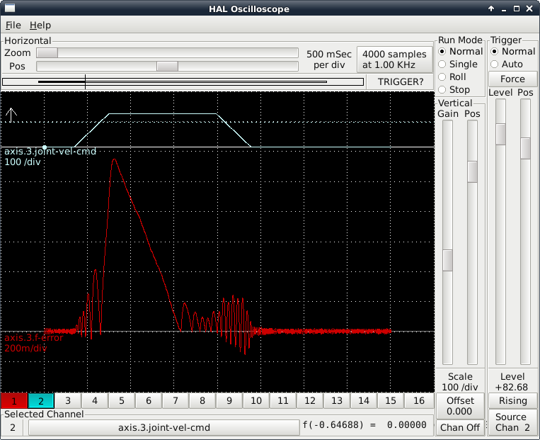
See attached. The screenshot is the execution of G91 G0 A180
Last edit: 13 Mar 2016 23:50 by Sparky961. Reason: Figured out how to put attached images inline
Please Log in or Create an account to join the conversation.
Time to create page: 0.129 seconds