Rotary table configuration
- Todd Zuercher
-

- Away
- Platinum Member
-

Less
More
- Posts: 4738
- Thank you received: 1451
11 Mar 2016 04:32 #71375
by Todd Zuercher
Replied by Todd Zuercher on topic Rotary table configuration
Current mode I believe you will find that it is significantly harder to tune. The first time I tried I struggled for a long time and I was never very happy with the stiffness or smoothness of the result using just a regular PID loop. The best success that I've had was to set up 2 PID loops with a fast loop running in a floating point basethread and a slow loop in the servo thread. The servo thread PID loop is set up like a normal velocity drive PID loop except instead of out-puting a velocity command to the drive, it send it to the fast loop. The fast loop handling the velocity loop (only needs P and D) outputs the torque (or current) command to the drive. It worked a lot better for me.
I would suggest trying to get encoder feed back to the drive and running them in velocity mode. Also I'd suggest tuning your loop using PID error rather than following error, since that is what the loop uses. They aren't always the same (one may be a thread period different from the other one).
I would suggest trying to get encoder feed back to the drive and running them in velocity mode. Also I'd suggest tuning your loop using PID error rather than following error, since that is what the loop uses. They aren't always the same (one may be a thread period different from the other one).
Please Log in or Create an account to join the conversation.
- Sparky961
-
 Topic Author
- Offline
- Elite Member
-

Less
More
- Posts: 210
- Thank you received: 15
12 Mar 2016 01:40 - 14 Mar 2016 00:00 #71468
by Sparky961
So you weren't satisfied even with this convoluted setup?
I made a mistake earlier with the data sheet that I've been using from the start. The one I posted is for the BE12A6, while mine is a B12A6D. They look very similar and the part number is as well. I was looking at the picture and comparing pin names when I noticed a few were different.
Here's a link to the B12A6D datasheet
I need to take some time reading through the proper one and see if any information in there changes my plans.
Replied by Sparky961 on topic Rotary table configuration
The best success that I've had was to set up 2 PID loops with a fast loop running in a floating point basethread and a slow loop in the servo thread.
So you weren't satisfied even with this convoluted setup?
I would suggest trying to get encoder feed back to the drive and running them in velocity mode.
I made a mistake earlier with the data sheet that I've been using from the start. The one I posted is for the BE12A6, while mine is a B12A6D. They look very similar and the part number is as well. I was looking at the picture and comparing pin names when I noticed a few were different.
Here's a link to the B12A6D datasheet
I need to take some time reading through the proper one and see if any information in there changes my plans.
Last edit: 14 Mar 2016 00:00 by Sparky961.
Please Log in or Create an account to join the conversation.
- Sparky961
-
Topic Author
- Offline
- Elite Member
-
Less
More
- Posts: 210
- Thank you received: 15
12 Mar 2016 02:00 #71471
by Sparky961
Replied by Sparky961 on topic Rotary table configuration
So, does one need a separate tachometer added to the motor if using tach feedback? If this is the case I think I'll try harder with tuning in current mode before going down that road.
Please Log in or Create an account to join the conversation.
- Todd Zuercher
-
- Away
- Platinum Member
-
Less
More
- Posts: 4738
- Thank you received: 1451
12 Mar 2016 20:29 #71502
by Todd Zuercher
Replied by Todd Zuercher on topic Rotary table configuration
I am pretty happy with it now, but it took me a long time to get there. (not knowing what I was doing.)
I fiddled with it for months with a single loop, and everything was a compromise, If it was stiff it hummed to much, quiet and smooth, then the following error was too much... Maybe I was being too picky. Also in torque mode with the single loop, none of the FF1 and 2 did not behave quite right (FF2 acted more like FF3). It was very sensitive and temperamental and I was never able to get a halscope trace that would look like anything in any tutorial.
When I switched it to the dual loop it calmed down and in one afternoon of messing with arround was stiffer and quieter than I was ever able to get it with the single loop.
I think you have a few options to set up a velocity output, you could try a double loop in Linuxcnc, get a tach to put on the motors and drives, or you could output a synthetic tach signal to the drives from Linuxcnc. The problem with this is you need two analog outputs to each drive. (Fanuc used to do it this way 30 years ago)
Here is a link to a thread where I was seeking help tuning the drives with a single PID loop. (lots of Halscope Screen shots)
forum.linuxcnc.org/forum/10-advanced-con...ning-advice?start=30
Here is another like to a thread where I'm starting tuning with 2 loops (5i25+7i77 combo)
forum.linuxcnc.org/forum/10-advanced-con...-velocity-loop#52619
The difference in the Halscope shots are significant. I have it even better now (only using P and D in the velocity loop now).
Here is a link to a place where I have the latest config posted.
forum.linuxcnc.org/forum/38-general-linu...e-questions?start=20
The following user(s) said Thank You: notJamesLee
Please Log in or Create an account to join the conversation.
- Sparky961
-
Topic Author
- Offline
- Elite Member
-
Less
More
- Posts: 210
- Thank you received: 15
13 Mar 2016 23:22 #71595
by Sparky961
Replied by Sparky961 on topic Rotary table configuration
Woa... that's a lot to absorb, but I'm thoroughly appreciative. I wouldn't have thought to try that approach but it sounds as though it was a good solution for you and possibly for me as well.
I'll get into the details and ask questions when I think I know enough to comment intelligently on it. I've been very impressed with everyone's willingness to help here. I probably would have given up in frustration long ago without it.
I'll get into the details and ask questions when I think I know enough to comment intelligently on it. I've been very impressed with everyone's willingness to help here. I probably would have given up in frustration long ago without it.
Please Log in or Create an account to join the conversation.
- Sparky961
-
Topic Author
- Offline
- Elite Member
-
Less
More
- Posts: 210
- Thank you received: 15
24 Mar 2016 22:26 #72115
by Sparky961
Replied by Sparky961 on topic Rotary table configuration
So, I'm going through the AXIS sections of your config files line by line and it occured to me that I have no idea where to start tuning when there are two different PID loops to tune. Do you start with velocity or position, or somehow both?
Please Log in or Create an account to join the conversation.
- Todd Zuercher
-
- Away
- Platinum Member
-
Less
More
- Posts: 4738
- Thank you received: 1451
25 Mar 2016 20:40 #72155
by Todd Zuercher
Replied by Todd Zuercher on topic Rotary table configuration
It is actually very similar to tuning an ordinary velocity drive. Where you tune the drives velocity loop first then tune the position loop in Linuxcnc. So here you tune the velocity loop in LInuxcnc first.
Please pardon, (I'm trying to remember what I did before and don't have access to the machine and any notes at work)
What you want to do is get a steady velocity command to the vel loop pid. The first time I did it by setting up a special config that bypassed the position loop, but I think you can get by with using the right settings in the position PID something like P=1 (or 10 something not too aggressive but enough to do something),I=0D=0,FF1=1,FF2=0. Once you are getting a steady command into the velocity loop PID, increase its P and D in the velocity PID loop till you get a reasonable response without overshoot (looking at velocity command into the vel-PID and velocity feedback your trying to get them to sort of match). Don't tune it very aggressively, you want it smooth, the Position loop can pick up the slack.
After that then tune the position loop, just like all the normal tuning tutorials.
Please Log in or Create an account to join the conversation.
- Sparky961
-
Topic Author
- Offline
- Elite Member
-
Less
More
- Posts: 210
- Thank you received: 15
28 Mar 2016 23:25 #72273
by Sparky961
Replied by Sparky961 on topic Rotary table configuration
I think I understand what you're saying, but just to confirm in my own words...
- Set up POS_PID with minimum values that "do something" (as in cause motion)
- Progressively increase VEL_PID parameters and tune such that a long "cruise" provides steady, consistent velocity (does fast or slow matter here? Test both?) Don't worry about position, at this point.
- Tune POS_PID parameters as was attempted previously, though monitoring slightly different signals (have to check back for what you suggested)
Sound right? It's been really nice out lately so I've been outside getting some sunshine instead of in the dark dingy shop "playing" with CNC.")
- Set up POS_PID with minimum values that "do something" (as in cause motion)
- Progressively increase VEL_PID parameters and tune such that a long "cruise" provides steady, consistent velocity (does fast or slow matter here? Test both?) Don't worry about position, at this point.
- Tune POS_PID parameters as was attempted previously, though monitoring slightly different signals (have to check back for what you suggested)
Sound right? It's been really nice out lately so I've been outside getting some sunshine instead of in the dark dingy shop "playing" with CNC.
Please Log in or Create an account to join the conversation.
- Sparky961
-
Topic Author
- Offline
- Elite Member
-
Less
More
- Posts: 210
- Thank you received: 15
29 Mar 2016 00:14 #72276
by Sparky961
Replied by Sparky961 on topic Rotary table configuration
Ok, here's my new baseline. Nasty, but I have to say that the motion does already seem more consistent. I'm getting HF oscillations and very slow motion compared to the last tuning attempt.
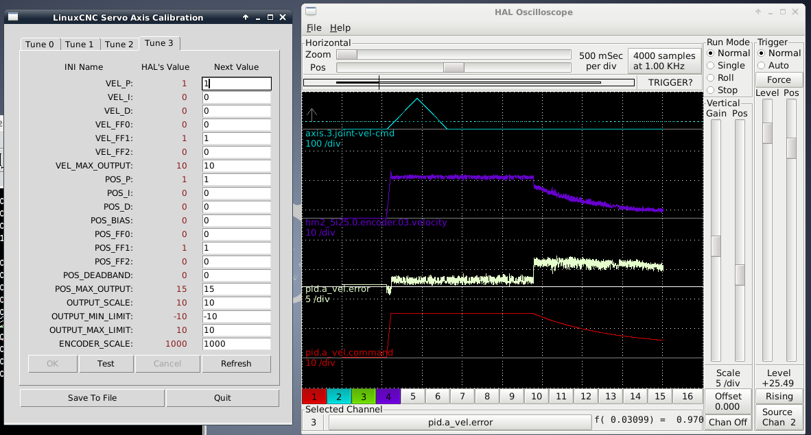
I'm running the following to trigger the scope:
Also a snippet of my INI and HAL for the axis I'm working on (complete "work in progress" files attached):
I'm running the following to trigger the scope:
G91 G0 A40Also a snippet of my INI and HAL for the axis I'm working on (complete "work in progress" files attached):
setp   pid.a_vel.Pgain     [AXIS_3]VEL_P
setp   pid.a_vel.Igain     [AXIS_3]VEL_I
setp   pid.a_vel.Dgain     [AXIS_3]VEL_D
setp   pid.a_vel.FF0       [AXIS_3]VEL_FF0
setp   pid.a_vel.FF1       [AXIS_3]VEL_FF1
setp   pid.a_vel.FF2       [AXIS_3]VEL_FF2
setp   pid.a_vel.maxoutput [AXIS_3]VEL_MAX_OUTPUT

setp   pid.a_pos.Pgain     [AXIS_3]POS_P
setp   pid.a_pos.Igain     [AXIS_3]POS_I
setp   pid.a_pos.Dgain     [AXIS_3]POS_D
setp   pid.a_pos.bias      [AXIS_3]POS_BIAS
setp   pid.a_pos.FF0       [AXIS_3]POS_FF0
setp   pid.a_pos.FF1       [AXIS_3]POS_FF1
setp   pid.a_pos.FF2       [AXIS_3]POS_FF2
setp   pid.a_pos.deadband  [AXIS_3]POS_DEADBAND
setp   pid.a_pos.maxoutput [AXIS_3]POS_MAX_OUTPUT

net a-index-enable  =>  pid.a_pos.index-enable
net a-enable       => pid.a_pos.enable => pid.a_vel.enable
net a-vel-output   <= pid.a_pos.output => pid.a_vel.command
net a-output       <= pid.a_vel.output
net a-pos-cmd      => pid.a_pos.command
net a-vel-fb       => pid.a_pos.feedback-deriv => pid.a_vel.feedback
net a-pos-fb       => pid.a_pos.feedback
[AXIS_3]
TYPE = ANGULAR
#WRAPPED_ROTARY = 1
HOME = 0.0
FERROR = 3600
MIN_FERROR = 3600
MAX_VELOCITY = 110.0
MAX_ACCELERATION = 550.0
VEL_P = 0
VEL_I = 0
VEL_D = 0
VEL_FF0 = 0
VEL_FF1 = 0
VEL_FF2 = 0
VEL_MAX_OUTPUT = 10
POS_P= 0
POS_I = 0
POS_D = 0
POS_FF0 = 0
POS_FF1 = 0
POS_FF2 = 0
POS_BIAS = 0
POS_DEADBAND= 0.000
POS_MAX_OUTPUT = 15
ENCODER_SCALE = 1000
OUTPUT_SCALE = 10.0
OUTPUT_MIN_LIMIT = -10.0
OUTPUT_MAX_LIMIT = 10.0
MIN_LIMIT = -9999.0
MAX_LIMIT = 9999.0
HOME_OFFSET = 0.0Please Log in or Create an account to join the conversation.
- Sparky961
-
Topic Author
- Offline
- Elite Member
-
Less
More
- Posts: 210
- Thank you received: 15
29 Mar 2016 00:17 - 29 Mar 2016 00:25 #72277
by Sparky961
Replied by Sparky961 on topic Rotary table configuration
Looking at your tuning screen shots, it appears that all three of the VEL parameters in the screen shot should overlay almost perfectly. Not quite there yet.
Last edit: 29 Mar 2016 00:25 by Sparky961.
Please Log in or Create an account to join the conversation.
Time to create page: 0.171 seconds