Rotary table configuration
- Sparky961
-
 Topic Author
- Offline
- Elite Member
-

Less
More
- Posts: 210
- Thank you received: 15
10 Mar 2016 04:54 - 13 Mar 2016 23:51 #71313
by Sparky961
Replied by Sparky961 on topic Rotary table configuration
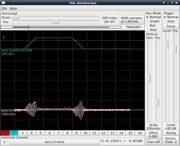
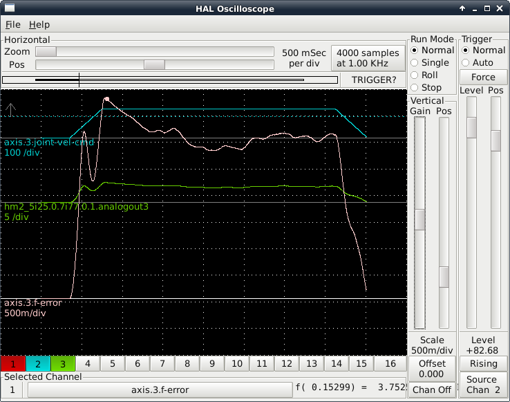
I should probably stop messing with it until I get some feedback, but the next step in at least one tutorial is to apply FF1 to minimize the following error. In trying this, I arrived at FF1=0.05 and ran exactly the same as above. Resulting plot attached (and looking much better).
I need to get rid of that noise though. Deadband perhaps, or something more?
I need to get rid of that noise though. Deadband perhaps, or something more?
Last edit: 13 Mar 2016 23:51 by Sparky961. Reason: Figured out how to put attached images inline
Please Log in or Create an account to join the conversation.
- Sparky961
-
Topic Author
- Offline
- Elite Member
-
Less
More
- Posts: 210
- Thank you received: 15
10 Mar 2016 05:21 - 13 Mar 2016 23:51 #71317
by Sparky961
Replied by Sparky961 on topic Rotary table configuration
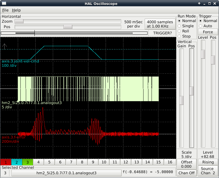
One last post before I'm off to bed tonight. I added hm2_5i25.0.7i77.0.1.analogout3 to the scope and it confirmed what I thought I had been seeing watching the value on the meter. It isn't smoothly being controlled in fine analog steps. Rather, it's a step waveform hitting min/max at a fast rate.
I don't know whether to check the chicken or the egg.... Best I head off for some rest now though. As always, you have no idea how much I'm appreciating your assistance with this. I will crack this egg (just to complete the analogy).
(This plot was captured under same conditions as the first one - eg. FF1 = 0, though I had been adjusting REF IN GAIN on the amp to see if I could reduce/eliminate the noise).
Last edit: 13 Mar 2016 23:51 by Sparky961. Reason: Figured out how to put attached images inline
Please Log in or Create an account to join the conversation.
- Todd Zuercher
-

- Away
- Platinum Member
-

Less
More
- Posts: 4759
- Thank you received: 1461
10 Mar 2016 13:48 #71335
by Todd Zuercher
Replied by Todd Zuercher on topic Rotary table configuration
This is turning into a servo tuning tutorial. (and that is perfectly OK.)
Do you know if the drives are velocity or torque (current) command input?
Maybe you could share what the PID settings were that go with the hal scope screen shots you've shared above, then we can probably give some suggestions what to try next? From the above shots I suspect there is too much or too little D or too much P or a combination of both but it is hard to say without knowing what changed by how much between the different screen shots.
Please Log in or Create an account to join the conversation.
- Sparky961
-
Topic Author
- Offline
- Elite Member
-
Less
More
- Posts: 210
- Thank you received: 15
10 Mar 2016 22:25 - 13 Mar 2016 23:53 #71358
by Sparky961
Replied by Sparky961 on topic Rotary table configuration
If its shaping up like a bit of a tutorial, that's a bit intentional. The thing about all the tutorials I've found so far and as a general rule is that they showcase everything going right. That isn't how things usually happen - at least not the first time around. My own efforts along with the help of those who know should add to the publicly accessible knowledge for the next guy that's completely green with this.
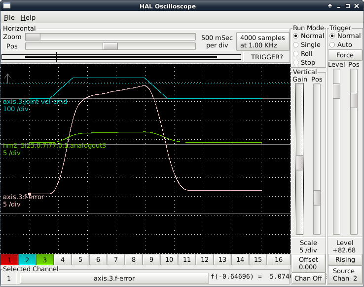
The PID parameters for the 1st and 3rd screen shots were the same as what I had listed earlier in this thread , except with P increased to the point where the table had begun to move (P = 10000, OTHERS = 0). I'm not sure how it can be possible that P is too high because the output isn't even reaching the maximum +/- 10V yet.
I think the last screen shot is the most illustrative because it's showing the output switching between +5 and -5 with nothing in between. I would expect a value close to zero when the error is small, gradually increasing and decreasing proportional to the error. But instead it pegs the output to min or max. I can confirm this if anyone questions it, but I'm pretty sure that with a lower P value the output would be lower but still be switching between the min/max with no gradual change. I can accept that this might be because the P is too high and it's saturating in either direction, but then I need a different strategy to arrive at an initial P value than what was originally suggested - or something. This is where I'm left scratching my head.
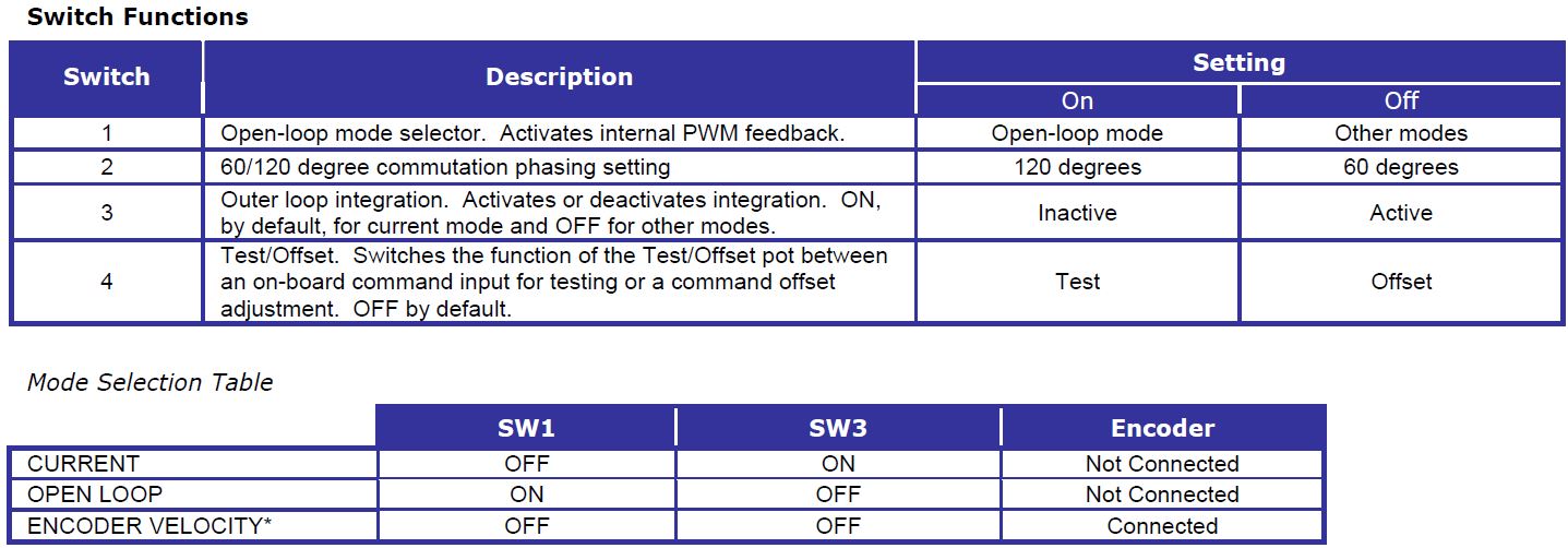
To the best of my knowledge, I'm operating the amp(s) in current mode. I've attached the data sheet and in the same earlier post mentioned above I detail how I've gone about setting up the amp prior to beginning tuning.
** EDIT **
The attached PDF is not correct for the amps I'm using but I'll leave it here for thread continuity. Read on in this thread if you need the right one.
The PID parameters for the 1st and 3rd screen shots were the same as what I had listed earlier in this thread , except with P increased to the point where the table had begun to move (P = 10000, OTHERS = 0). I'm not sure how it can be possible that P is too high because the output isn't even reaching the maximum +/- 10V yet.
I think the last screen shot is the most illustrative because it's showing the output switching between +5 and -5 with nothing in between. I would expect a value close to zero when the error is small, gradually increasing and decreasing proportional to the error. But instead it pegs the output to min or max. I can confirm this if anyone questions it, but I'm pretty sure that with a lower P value the output would be lower but still be switching between the min/max with no gradual change. I can accept that this might be because the P is too high and it's saturating in either direction, but then I need a different strategy to arrive at an initial P value than what was originally suggested - or something. This is where I'm left scratching my head.
To the best of my knowledge, I'm operating the amp(s) in current mode. I've attached the data sheet and in the same earlier post mentioned above I detail how I've gone about setting up the amp prior to beginning tuning.
** EDIT **
The attached PDF is not correct for the amps I'm using but I'll leave it here for thread continuity. Read on in this thread if you need the right one.
Last edit: 13 Mar 2016 23:53 by Sparky961.
Please Log in or Create an account to join the conversation.
- Sparky961
-
Topic Author
- Offline
- Elite Member
-
Less
More
- Posts: 210
- Thank you received: 15
10 Mar 2016 22:29 #71359
by Sparky961
Replied by Sparky961 on topic Rotary table configuration
Oh, and if I keep referring to another tutorial I'm attempting to follow, this is the one:
gnipsel.com/linuxcnc/tuning/servo.html
gnipsel.com/linuxcnc/tuning/servo.html
Please Log in or Create an account to join the conversation.
- PCW
-

- Offline
- Moderator
-

Less
More
- Posts: 17985
- Thank you received: 5277
10 Mar 2016 22:35 - 10 Mar 2016 22:39 #71361
by PCW
Replied by PCW on topic Rotary table configuration
pncconf has a bug for servo systems where is sets the maximum error bound to 0.0005:
setp pid.x.maxerror .0005
you will need to set these all to 0 ( meaning no bounding )
to get any kind of reasonable behavior
BTW P is probably much too high, its just that with a maxerror of .0005 you need a P of 10000 (*0.0005) to get a 5V signal
setp pid.x.maxerror .0005
you will need to set these all to 0 ( meaning no bounding )
to get any kind of reasonable behavior
BTW P is probably much too high, its just that with a maxerror of .0005 you need a P of 10000 (*0.0005) to get a 5V signal
Last edit: 10 Mar 2016 22:39 by PCW.
Please Log in or Create an account to join the conversation.
- Sparky961
-
Topic Author
- Offline
- Elite Member
-
Less
More
- Posts: 210
- Thank you received: 15
10 Mar 2016 23:49 - 11 Mar 2016 00:48 #71364
by Sparky961
I am infinitely grateful for this information and it completely explains what I was observing. Setting these to "0" and starting over working my way up from P=0.001 was an ENTIRELY DIFFERENT EXPERIENCE than before. One finds it hard to avoid questioning why this bug still exists, but one will set that aside having been involved with software development in the past and knowing how long the list of bugs can get.
For the next couple of screenshot descriptions, the test is as before
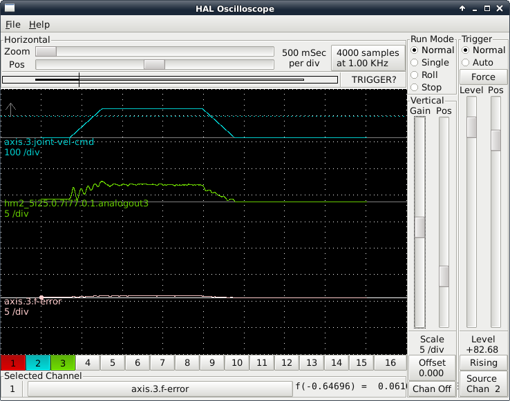
Screenshot #1: Ok, so now my table begins to rotate with P=0.1, but just barely. The following error is pretty bad and it never quite makes it to the commanded position. Following error increases throughout the move to a maximum of about 33 degrees right at the point where we begin deceleration. The analog output is MUCH, MUCH better now. Even in caps this is an understatement!
Screenshot #2: Increased to P=1 and the following error drops significantly. The final position becomes much more accurate as well. I'm definitely noticing the beginnings of oscillation on the acceleration and maybe a bit on the deceleration too.

Screenshot #3: Increased to P=10 and was rewarded with another decrease in following error. However, there is definite oscillation in there now and I'm beginning to wonder if this is too much P already. I wanted to keep all 3 screen shots at the same vertical scale to show difference but that makes it a bit hard to see that the following error is oscillating roughly proportional to the oscillation of the output.
I think I'm at the point now where I can return to a more standard "PID Tuning Tutorial" where most things are going right. Suggestions related to these screen shots and my next steps will be appreciated.
Replied by Sparky961 on topic Rotary table configuration
pncconf has a bug for servo systems where is sets the maximum error bound to 0.0005:
setp pid.x.maxerror .0005
you will need to set these all to 0 ( meaning no bounding )
to get any kind of reasonable behavior
BTW P is probably much too high, its just that with a maxerror of .0005 you need a P of 10000 (*0.0005) to get a 5V signal
I am infinitely grateful for this information and it completely explains what I was observing. Setting these to "0" and starting over working my way up from P=0.001 was an ENTIRELY DIFFERENT EXPERIENCE than before. One finds it hard to avoid questioning why this bug still exists, but one will set that aside having been involved with software development in the past and knowing how long the list of bugs can get.
For the next couple of screenshot descriptions, the test is as before
MDI: G91 G0 A180Screenshot #1: Ok, so now my table begins to rotate with P=0.1, but just barely. The following error is pretty bad and it never quite makes it to the commanded position. Following error increases throughout the move to a maximum of about 33 degrees right at the point where we begin deceleration. The analog output is MUCH, MUCH better now. Even in caps this is an understatement!
Screenshot #2: Increased to P=1 and the following error drops significantly. The final position becomes much more accurate as well. I'm definitely noticing the beginnings of oscillation on the acceleration and maybe a bit on the deceleration too.
Screenshot #3: Increased to P=10 and was rewarded with another decrease in following error. However, there is definite oscillation in there now and I'm beginning to wonder if this is too much P already. I wanted to keep all 3 screen shots at the same vertical scale to show difference but that makes it a bit hard to see that the following error is oscillating roughly proportional to the oscillation of the output.
I think I'm at the point now where I can return to a more standard "PID Tuning Tutorial" where most things are going right. Suggestions related to these screen shots and my next steps will be appreciated.
Last edit: 11 Mar 2016 00:48 by Sparky961.
The following user(s) said Thank You: notJamesLee
Please Log in or Create an account to join the conversation.
- Sparky961
-
Topic Author
- Offline
- Elite Member
-
Less
More
- Posts: 210
- Thank you received: 15
11 Mar 2016 00:41 - 11 Mar 2016 00:46 #71366
by Sparky961
Replied by Sparky961 on topic Rotary table configuration
Before I move on to tuning other parameters, I thought I might have a look at a longer move. I'd like to observe it over a few rotations but I'm not sure how to make Halscope grab that many samples.
So I settled for one full rotation:
Note that because things are improving I've changed the scale of the following error from the last collection of screen shots.
Screenshot #1: Beginning with P=1, which I had thought might be my desired number, there's an overall deviation of about 1 degree throughout the cruise and a maximum following error of about 3.5 degrees. It looks kinda nasty if you ask me.
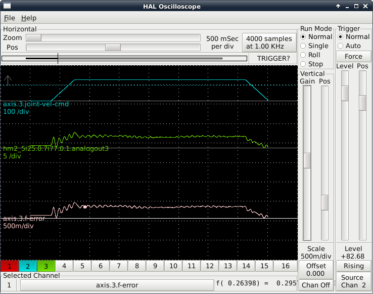
Screenshot #2: Going with the x10 theme of the last post, I set P=10 and tried again. This time the deviation and overall error are improved (decreased) but there's oscillation throughout the move. It is, however, much more consistent if you were to linearize the oscillations. following error peaks at about 0.4 right after the acceleration phase, and averages about 0.3 throughout the cruise. P/P of the oscillations is around 0.06 degrees.
Screenshot #3 I got tired of the x10 theme. I wanted to see where things started to get significantly different (and worse) because aside from the oscillation superimposed on the trace the overall error was getting better and better. So this one is with P=50 and it did get more interesting. I get pretty bad ringing at the acceleration and deceleration phases. In between though, it looks better than anything else yet. Peak following error is at the end of the acceleration, at 0.15 degrees. Throughout the cruise it averages 0.06 with a P/P of 0.01
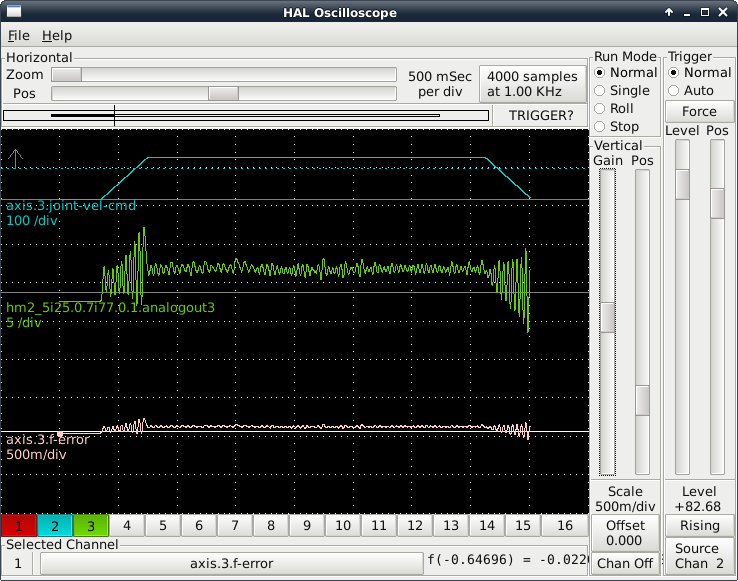
Any of this looking good yet? Have I pushed it too far? Am I looking at the right things? Should I be concerned about this oscillation superimposed on the trace?
So I settled for one full rotation:
G91 G0 A360Note that because things are improving I've changed the scale of the following error from the last collection of screen shots.
Screenshot #1: Beginning with P=1, which I had thought might be my desired number, there's an overall deviation of about 1 degree throughout the cruise and a maximum following error of about 3.5 degrees. It looks kinda nasty if you ask me.
Screenshot #2: Going with the x10 theme of the last post, I set P=10 and tried again. This time the deviation and overall error are improved (decreased) but there's oscillation throughout the move. It is, however, much more consistent if you were to linearize the oscillations. following error peaks at about 0.4 right after the acceleration phase, and averages about 0.3 throughout the cruise. P/P of the oscillations is around 0.06 degrees.
Screenshot #3 I got tired of the x10 theme. I wanted to see where things started to get significantly different (and worse) because aside from the oscillation superimposed on the trace the overall error was getting better and better. So this one is with P=50 and it did get more interesting. I get pretty bad ringing at the acceleration and deceleration phases. In between though, it looks better than anything else yet. Peak following error is at the end of the acceleration, at 0.15 degrees. Throughout the cruise it averages 0.06 with a P/P of 0.01
Any of this looking good yet? Have I pushed it too far? Am I looking at the right things? Should I be concerned about this oscillation superimposed on the trace?
Last edit: 11 Mar 2016 00:46 by Sparky961.
Please Log in or Create an account to join the conversation.
- PCW
-
- Offline
- Moderator
-
Less
More
- Posts: 17985
- Thank you received: 5277
11 Mar 2016 00:55 #71369
by PCW
Replied by PCW on topic Rotary table configuration
At this point it would help t to know whether you have velocity or torque mode drives
Do the drives have tachometers?
The plots look more like velocity mode or maybe just voltage mode to me
(voltage mode is somewhere in the middle between torque and velocity mode)
If these are velocity mode servos it may be that the velocity loop at the drive needs tuning
They do no look like current mode to me
If they are running in voltage mode, tuning is similar to velocity mode but you will have to add
D term for velocity feedback to control the oscillation (since the drives are not doing this themselves)
You should also tune out the position error when slewing with FF1
For voltage mode drives you can add some I term when everything else is tuned well
to eliminate any static error (DO NOT add I until all other parameters are very close to optimum)
Please Log in or Create an account to join the conversation.
- Sparky961
-
Topic Author
- Offline
- Elite Member
-
Less
More
- Posts: 210
- Thank you received: 15
11 Mar 2016 01:19 - 11 Mar 2016 01:32 #71371
by Sparky961
The datasheet lists 3 modes of operation: Current, Open Loop, and Encoder Velocity. SW1 and SW3 (a DIP switch) select the mode. I have confirmed that it is set to Current mode. (1=OFF, 2=ON, 3=ON, 4=OFF)
The encoder is not attached to the drive, only the 7i77 board. The HALL sensors do connect to the drive. But as far as I have determined, these are not using velocity mode.
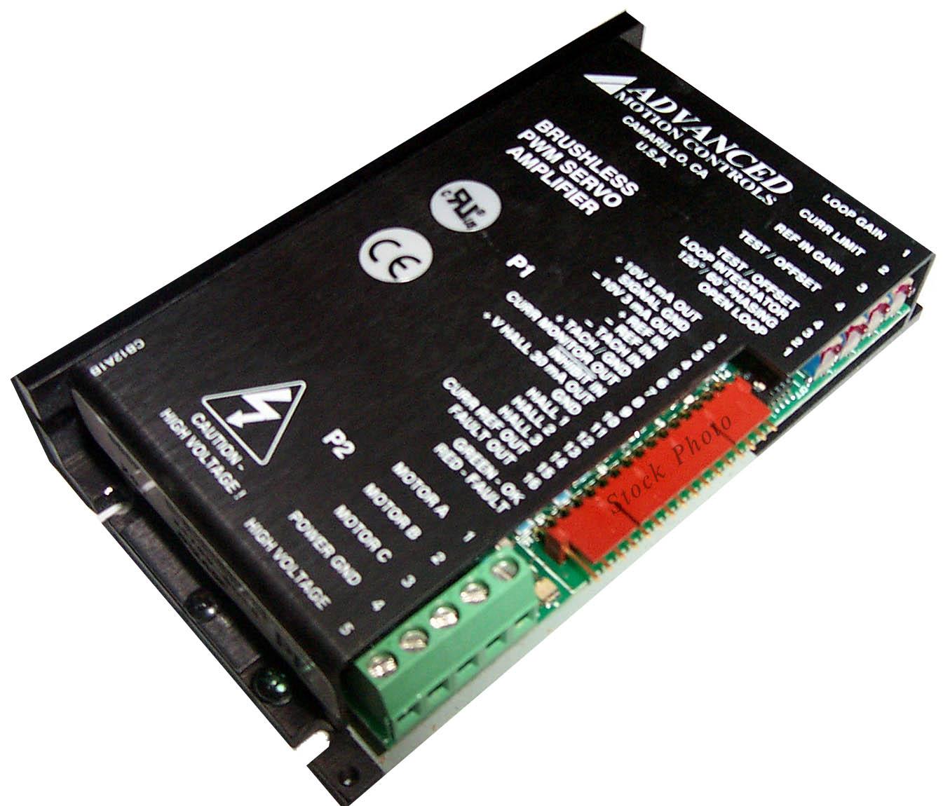
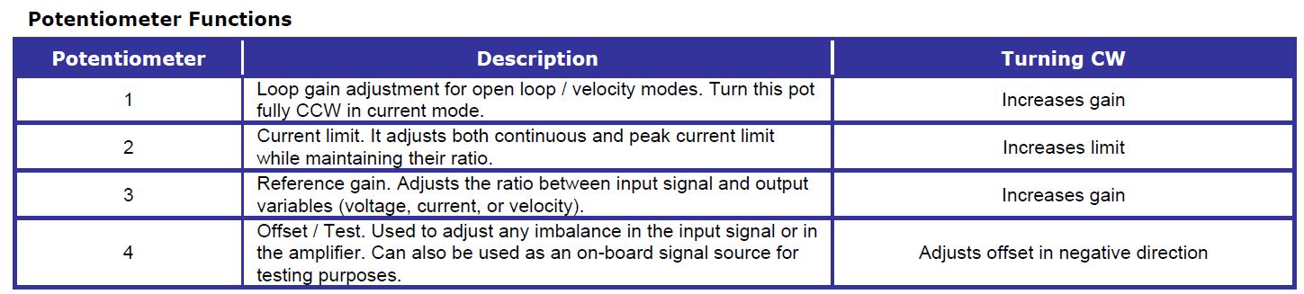
My confidence level drops if you were to ask about the initial settings of REF IN GAIN, OFFSET, and CURRENT LIMIT of the drive. I wonder if maybe REF IN GAIN is set too high and reducing it might help curb the oscillation. I could reduce the CURRENT LIMIT, as my experimenting has shown that having it high can produce violent oscillation. But I also suspect it's just making existing oscillation problems worse. I think it would help to have the highest possible current on a well-tuned system so it can produce the best correction response that's commanded. And no, I don't have a PhD in PID.
Replied by Sparky961 on topic Rotary table configuration
At this point it would help t to know whether you have velocity or torque mode drives
Do the drives have tachometers?
The plots look more like velocity mode or maybe just voltage mode to me
(voltage mode is somewhere in the middle between torque and velocity mode)
If these are velocity mode servos it may be that the velocity loop at the drive needs tuning
They do no look like current mode to me
If they are running in voltage mode, tuning is similar to velocity mode but you will have to add
D term for velocity feedback to control the oscillation (since the drives are not doing this themselves)
You should also tune out the position error when slewing with FF1
For voltage mode drives you can add some I term when everything else is tuned well
to eliminate any static error (DO NOT add I until all other parameters are very close to optimum)
The datasheet lists 3 modes of operation: Current, Open Loop, and Encoder Velocity. SW1 and SW3 (a DIP switch) select the mode. I have confirmed that it is set to Current mode. (1=OFF, 2=ON, 3=ON, 4=OFF)
The encoder is not attached to the drive, only the 7i77 board. The HALL sensors do connect to the drive. But as far as I have determined, these are not using velocity mode.
My confidence level drops if you were to ask about the initial settings of REF IN GAIN, OFFSET, and CURRENT LIMIT of the drive. I wonder if maybe REF IN GAIN is set too high and reducing it might help curb the oscillation. I could reduce the CURRENT LIMIT, as my experimenting has shown that having it high can produce violent oscillation. But I also suspect it's just making existing oscillation problems worse. I think it would help to have the highest possible current on a well-tuned system so it can produce the best correction response that's commanded. And no, I don't have a PhD in PID.
Last edit: 11 Mar 2016 01:32 by Sparky961.
Please Log in or Create an account to join the conversation.
Time to create page: 0.624 seconds