Rotary table configuration
- Sparky961
-
 Topic Author
- Offline
- Elite Member
-

Less
More
- Posts: 210
- Thank you received: 15
30 Mar 2016 23:50 #72424
by Sparky961
Perfect. That will help make debugging things much quicker.
Replied by Sparky961 on topic Rotary table configuration
I added the suggested debug lines to the end of my HAL file because I couldn't for the life of me figure out how to start a HAL command prompt while LinuxCNC was already running.
halcmd -kf
Perfect. That will help make debugging things much quicker.
Please Log in or Create an account to join the conversation.
- Sparky961
-
Topic Author
- Offline
- Elite Member
-
Less
More
- Posts: 210
- Thank you received: 15
31 Mar 2016 00:00 #72425
by Sparky961
Aside from the noise we've been talking about, I'm pretty happy with how it's working and it is so much better than before I tried the two PID loops. I'm sure there's some more tweaking I'll do in the future but until I start making chips I could just be chasing my tail trying to make it better.
Here's (hopefully) one last screen shot to end this saga. Its an arbitrary step sequence that includes motion near the maximum I can move and some closer to the bottom. The PID VEL output seems to mirror the PID ERROR. Is this what you'd expect to see, or does this indicate a problem?
All of the motion in the screenshot happens in about 1.4 seconds, which is likely quicker than I'll be using the rotary axis.
Replied by Sparky961 on topic Rotary table configuration
If what you had before was looking good enough for you then run with it.
As far as how fast to test at I don't know, I would think that somewhere in the range of speed you'd expect to use most. Most of the tuning instructions for drive tuning I've looked at only use a relatively small move at a moderately slow speed, but with a square wave input, and you are trying to get the move to match as closely as possible to the command.
One more thing that might be informative to look at is what does the output to the amp look like?
pid.a_vel.output
Just to make sure your not saturating your torque command or bouncing off the hi low (+/-10v) limits.
Aside from the noise we've been talking about, I'm pretty happy with how it's working and it is so much better than before I tried the two PID loops. I'm sure there's some more tweaking I'll do in the future but until I start making chips I could just be chasing my tail trying to make it better.
Here's (hopefully) one last screen shot to end this saga. Its an arbitrary step sequence that includes motion near the maximum I can move and some closer to the bottom. The PID VEL output seems to mirror the PID ERROR. Is this what you'd expect to see, or does this indicate a problem?
All of the motion in the screenshot happens in about 1.4 seconds, which is likely quicker than I'll be using the rotary axis.
G90
G1 F6600 A10
G1 F6600 A0
G1 F6600 A30
G1 F6600 A0
G1 F2200 A5
G1 F2200 A0
G1 F750 A2
G1 F750 A0
M2
Please Log in or Create an account to join the conversation.
- Sparky961
-
Topic Author
- Offline
- Elite Member
-
Less
More
- Posts: 210
- Thank you received: 15
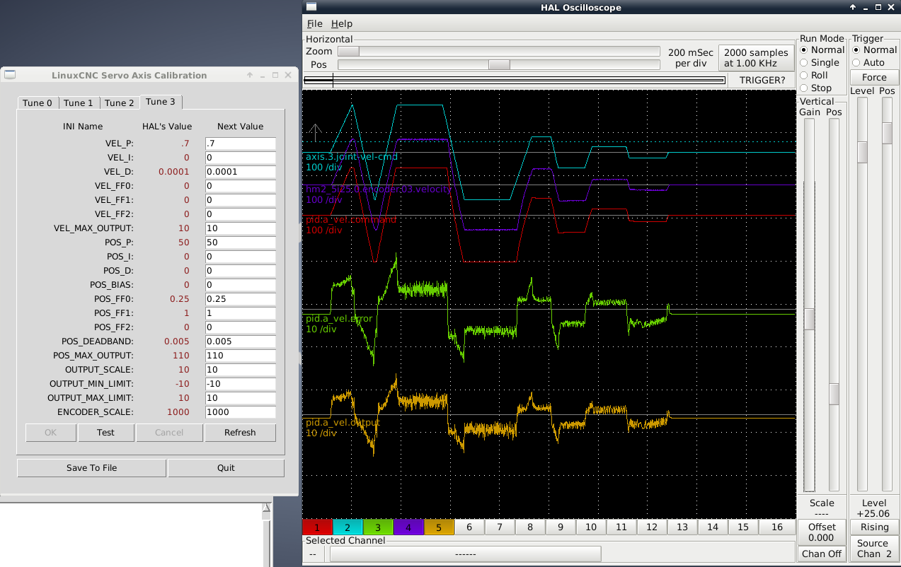
31 Mar 2016 01:07 #72428
by Sparky961
Replied by Sparky961 on topic Rotary table configuration
There were a few things I just discovered that weren't right with the last setup. For starters at slow cruising velocity the following error would creep higher. Removing FF0 caused f-error to immediately jump down to about 0.01.
On long cruises at high speeds I was seeing f-error increase linearly over the distance. This indicated to me that I couldn't keep up with the commanded position, so I've reduced the maximum velocity to just below a new experimentally-determined maximum (90 deg/s or 5400 deg/min). This has dramatically decreased the following error, as recorded using the minmax component.
Same arbitrary step program but with reduced max velocity compared to the first time, and some other changes to the parameters as seen in the screen shot:

Am I trapped in my own PID loop? Tune, inspect, tweak, tune, inspect, tweak......")
On long cruises at high speeds I was seeing f-error increase linearly over the distance. This indicated to me that I couldn't keep up with the commanded position, so I've reduced the maximum velocity to just below a new experimentally-determined maximum (90 deg/s or 5400 deg/min). This has dramatically decreased the following error, as recorded using the minmax component.
Same arbitrary step program but with reduced max velocity compared to the first time, and some other changes to the parameters as seen in the screen shot:
Am I trapped in my own PID loop? Tune, inspect, tweak, tune, inspect, tweak......
Please Log in or Create an account to join the conversation.
- andypugh
-

- Offline
- Moderator
-

Less
More
- Posts: 19861
- Thank you received: 4636
31 Mar 2016 08:52 #72443
by andypugh
It happens...
Replied by andypugh on topic Rotary table configuration
Am I trapped in my own PID loop? Tune, inspect, tweak, tune, inspect, tweak......
It happens...
Please Log in or Create an account to join the conversation.
Time to create page: 0.157 seconds