Search Results (Searched for: )
- partec
- partec
09 Dec 2024 11:12
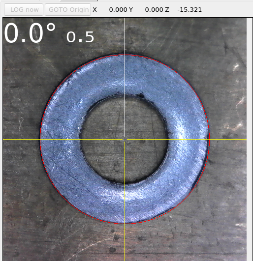
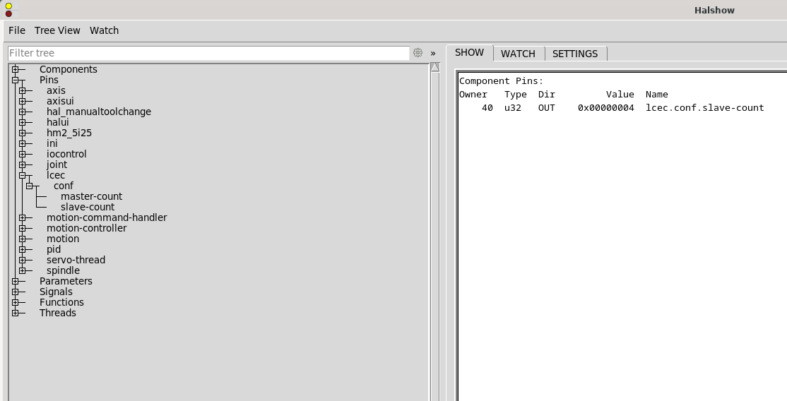
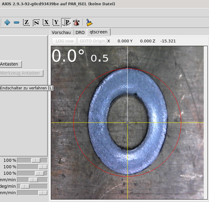
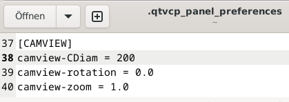
Replied by partec on topic camera resolution doesn' fit
camera resolution doesn' fit
Category: Qtvcp
- my1987toyota

09 Dec 2024 10:49
FreeCAD 1.0 Who's using it? was created by my1987toyota
FreeCAD 1.0 Who's using it?
Category: CAD CAM
- vibram
- vibram
09 Dec 2024 09:36 - 09 Dec 2024 09:36
Replied by vibram on topic Ethercat-conf.xml with beckhoff el1008
Ethercat-conf.xml with beckhoff el1008
Category: EtherCAT
- abdulasis12
- abdulasis12
09 Dec 2024 08:55
Replied by abdulasis12 on topic Feedback control XY not full speed run G1 when curve or Arc
Feedback control XY not full speed run G1 when curve or Arc
Category: General LinuxCNC Questions
- meister
- meister
09 Dec 2024 08:41
Replied by meister on topic LinuxCNC-RIO - RealtimeIO for LinuxCNC based on FPGA (ICE40 / ECP5)
LinuxCNC-RIO - RealtimeIO for LinuxCNC based on FPGA (ICE40 / ECP5)
Category: Computers and Hardware
- MirkoCNC
- MirkoCNC
09 Dec 2024 08:23
Replied by MirkoCNC on topic LinuxCNC-RIO - RealtimeIO for LinuxCNC based on FPGA (ICE40 / ECP5)
LinuxCNC-RIO - RealtimeIO for LinuxCNC based on FPGA (ICE40 / ECP5)
Category: Computers and Hardware
- partec
- partec
09 Dec 2024 08:18 - 09 Dec 2024 10:46
Replied by partec on topic camera resolution doesn' fit
camera resolution doesn' fit
Category: Qtvcp

- MirkoCNC
- MirkoCNC
09 Dec 2024 08:16
Replied by MirkoCNC on topic LinuxCNC-RIO - RealtimeIO for LinuxCNC based on FPGA (ICE40 / ECP5)
LinuxCNC-RIO - RealtimeIO for LinuxCNC based on FPGA (ICE40 / ECP5)
Category: Computers and Hardware
- cmorley
- cmorley
09 Dec 2024 04:26
- snowgoer540

09 Dec 2024 04:11
- fully_defined

09 Dec 2024 01:18

- jmelson
- jmelson
09 Dec 2024 00:53
Replied by jmelson on topic Kuka robot project - hardware choice
Kuka robot project - hardware choice
Category: Driver Boards
- JT

09 Dec 2024 00:47
- jmelson
- jmelson
09 Dec 2024 00:46
Replied by jmelson on topic Kuka robot project - hardware choice
Kuka robot project - hardware choice
Category: Driver Boards
- jmelson
- jmelson
09 Dec 2024 00:42
Replied by jmelson on topic Kuka robot project - hardware choice
Kuka robot project - hardware choice
Category: Driver Boards
Time to create page: 0.444 seconds