Search Results (Searched for: )
- Bari

20 Jul 2024 06:41
Replied by Bari on topic New and Working RTAI debs for 2.9
New and Working RTAI debs for 2.9
Category: Installing LinuxCNC
- PCW

20 Jul 2024 04:31
- vre
- vre
20 Jul 2024 04:19 - 20 Jul 2024 04:23
- PCW
20 Jul 2024 02:44
- shasse
- shasse
20 Jul 2024 02:32
Replied by shasse on topic "error finishing read" with Mesa 7i92T on fresh install
"error finishing read" with Mesa 7i92T on fresh install
Category: Driver Boards
- Project_Hopeless

20 Jul 2024 01:19
- tommylight

20 Jul 2024 00:32 - 20 Jul 2024 00:37
Replied by tommylight on topic Remora - ethernet NVEM / EC300 / EC500 cnc board
Remora - ethernet NVEM / EC300 / EC500 cnc board
Category: Computers and Hardware
- scotta

19 Jul 2024 22:20
Replied by scotta on topic Remora - ethernet NVEM / EC300 / EC500 cnc board
Remora - ethernet NVEM / EC300 / EC500 cnc board
Category: Computers and Hardware
- PCW
19 Jul 2024 21:48 - 19 Jul 2024 23:01
Replied by PCW on topic 7i96 non S PWM on an output possible?
7i96 non S PWM on an output possible?
Category: Driver Boards
- PCW
19 Jul 2024 21:42 - 19 Jul 2024 21:42
Replied by PCW on topic "error finishing read" with Mesa 7i92T on fresh install
"error finishing read" with Mesa 7i92T on fresh install
Category: Driver Boards
- my1987toyota

19 Jul 2024 21:32
Replied by my1987toyota on topic 7i96 non S PWM on an output possible?
7i96 non S PWM on an output possible?
Category: Driver Boards
- PCW
19 Jul 2024 19:48 - 19 Jul 2024 21:14
Replied by PCW on topic MesaCT config - Help
MesaCT config - Help
Category: General LinuxCNC Questions
- Finngineering
- Finngineering
19 Jul 2024 19:32
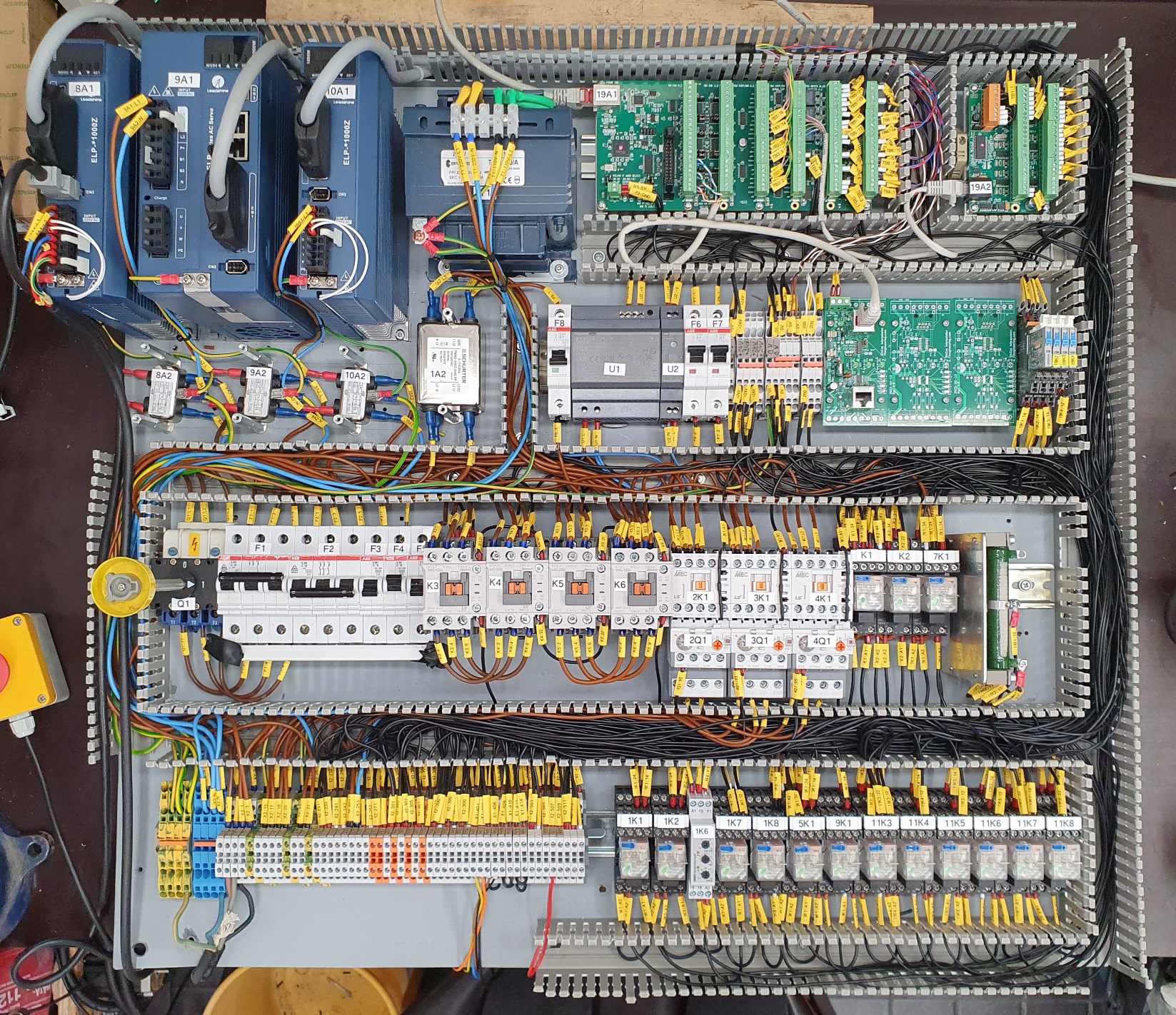
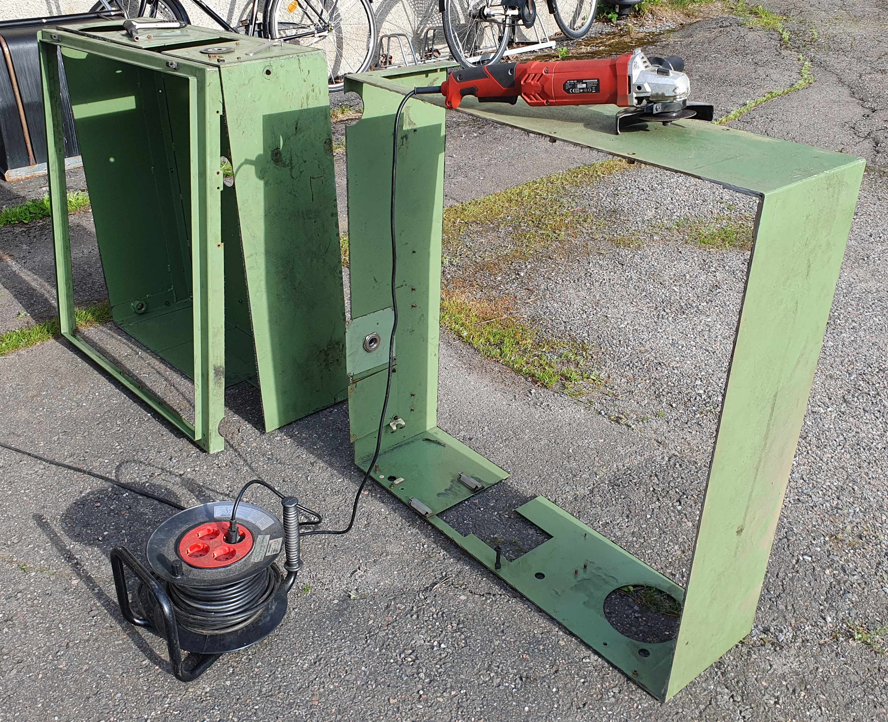
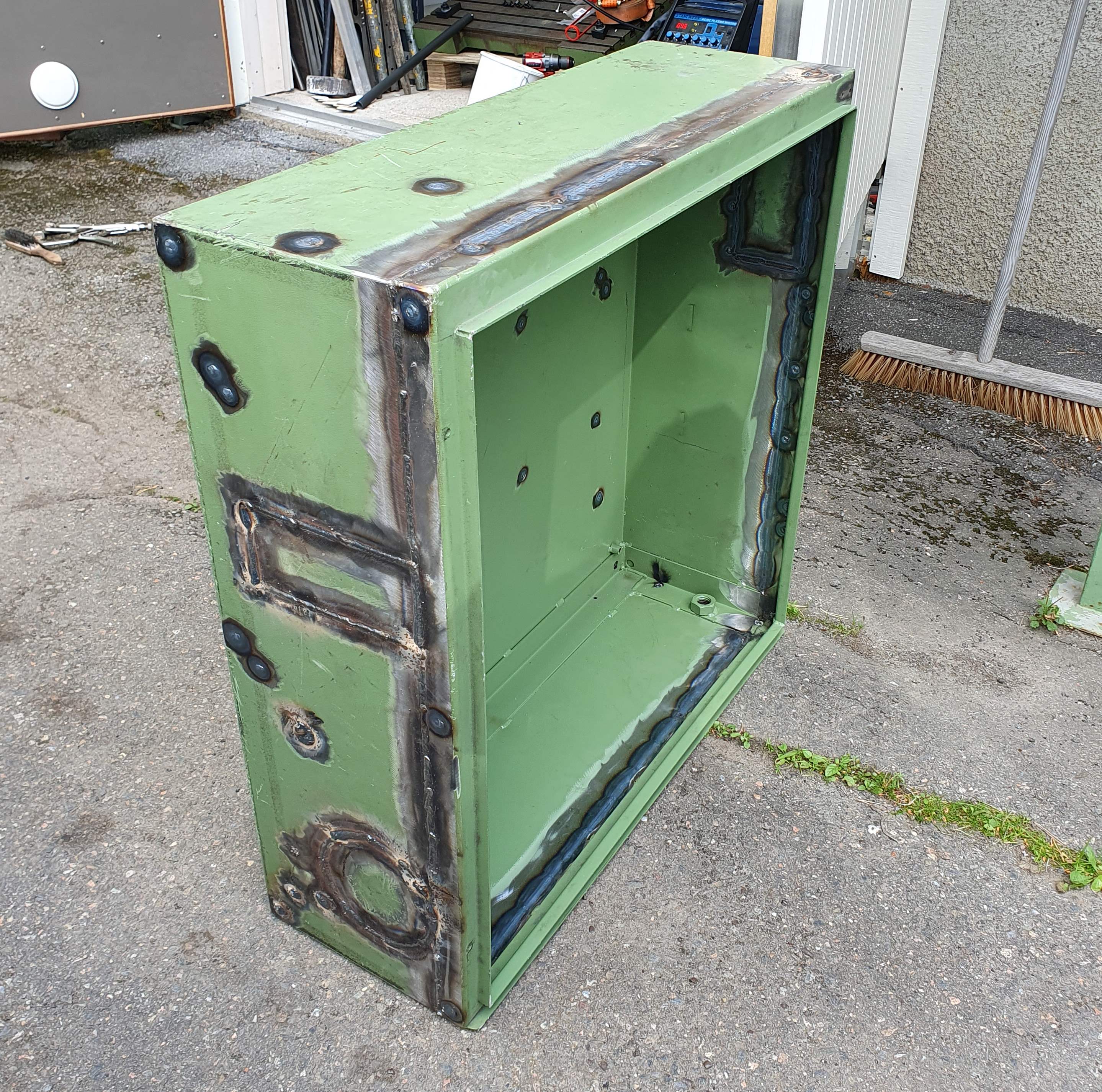
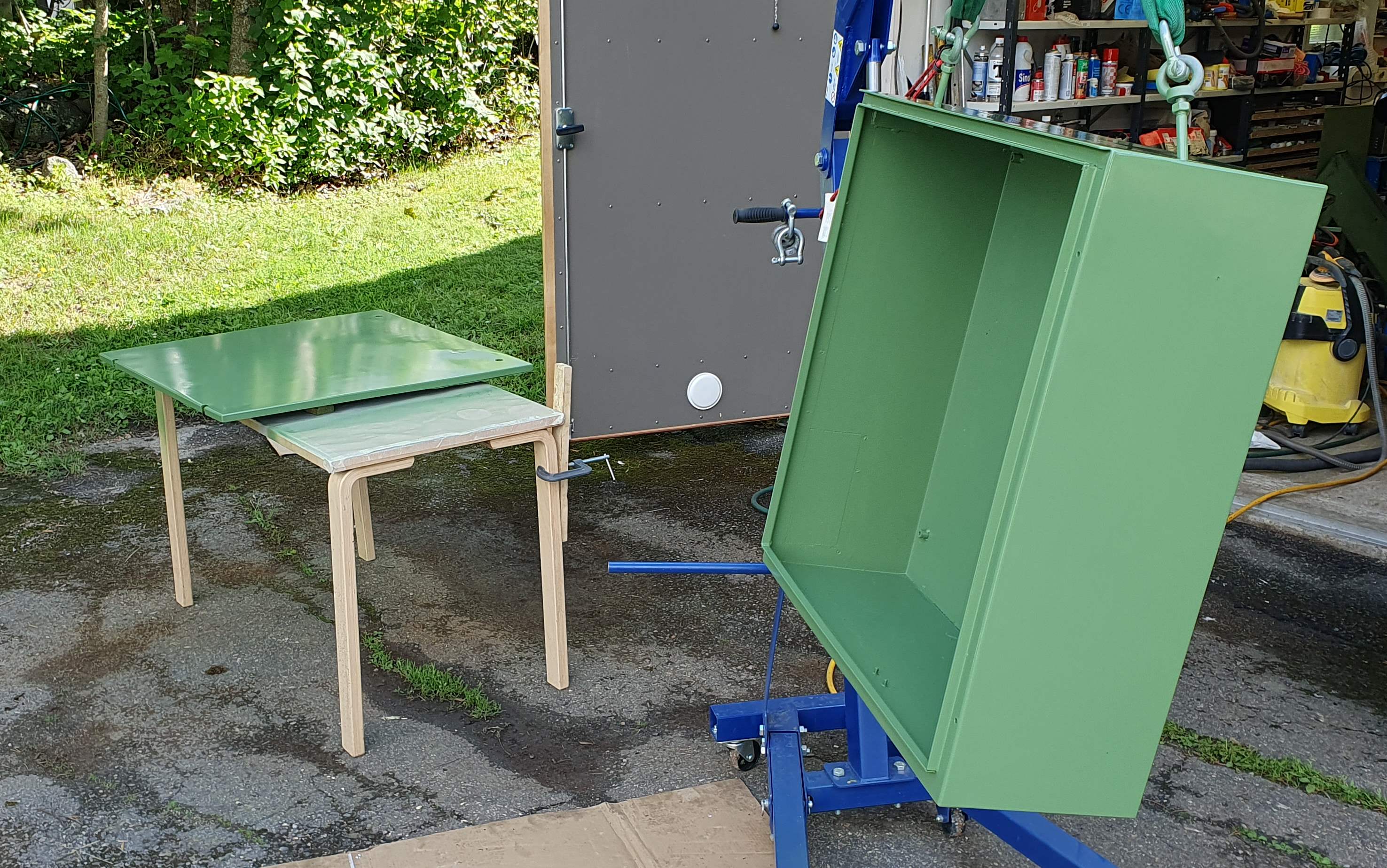
Replied by Finngineering on topic Un-lobotomizing a Maho MH600T
Un-lobotomizing a Maho MH600T
Category: CNC Machines
- Finngineering
- Finngineering
19 Jul 2024 19:23
Replied by Finngineering on topic Un-lobotomizing a Maho MH600T
Un-lobotomizing a Maho MH600T
Category: CNC Machines
- Aciera

19 Jul 2024 17:42
Replied by Aciera on topic Brauche bitte Hilfe bei der Steuerung des Werkzeugrevolvers
Brauche bitte Hilfe bei der Steuerung des Werkzeugrevolvers
Category: Deutsch
Time to create page: 0.579 seconds