Un-lobotomizing a Maho MH600T
- Finngineering
- Offline
- Senior Member
-

Less
More
- Posts: 53
- Thank you received: 34
11 Apr 2024 20:02 #298026
by Finngineering
Replied by Finngineering on topic Un-lobotomizing a Maho MH600T
I also had that thought at first. But when I looked up the LS703 scale, I found that they should also have a ~100 mA bulb:
siebert-automation.com/wp-content/upload...ing-Instructions.pdf
You could maybe connect the scale without the ic-nv if you have a board like that and check the current draw. In that case, only the bulb in the scale should be taking some power/current.
siebert-automation.com/wp-content/upload...ing-Instructions.pdf
You could maybe connect the scale without the ic-nv if you have a board like that and check the current draw. In that case, only the bulb in the scale should be taking some power/current.
Please Log in or Create an account to join the conversation.
- vre
- Offline
- Platinum Member
-

Less
More
- Posts: 610
- Thank you received: 17
11 Apr 2024 20:55 #298028
by vre
Replied by vre on topic Un-lobotomizing a Maho MH600T
I will do more checks for current draw..
These old heidenhain scales are more reliable than cheap chinese 5um quadrature ttl scales ?
These old heidenhain scales are more reliable than cheap chinese 5um quadrature ttl scales ?
Please Log in or Create an account to join the conversation.
- Finngineering
- Offline
- Senior Member
-

Less
More
- Posts: 53
- Thank you received: 34
12 Apr 2024 06:19 #298044
by Finngineering
Replied by Finngineering on topic Un-lobotomizing a Maho MH600T
I haven't really made any comparison. But I would for sure prefer old Heidenhains over new "chinese" 5 µm scales. For my mill, I do want the 1µm resolution. I could also imagine that the actual accuracy (over length) is better with the Heidenhain scales.
Please Log in or Create an account to join the conversation.
- RotarySMP
-

- Offline
- Platinum Member
-

Less
More
- Posts: 1542
- Thank you received: 572
12 Apr 2024 17:38 #298090
by RotarySMP
Replied by RotarySMP on topic Un-lobotomizing a Maho MH600T
I got the original Heidenhain production calibration reports with my Maho. The worst of the three, had a worst deviation of 0.4 µm if I recall correctly. It would be interesting to calibrate a chinese 1µm scale and see how accurate they are. I would not be surprised if they easily exceed the accuracy achieved by Heidenhain 50 years ago.
Please Log in or Create an account to join the conversation.
- Aciera
-

- Offline
- Administrator
-

Less
More
- Posts: 4649
- Thank you received: 2070
12 Apr 2024 18:00 - 12 Apr 2024 18:00 #298092
by Aciera
Replied by Aciera on topic Un-lobotomizing a Maho MH600T
According to the certificates of my three 5um glass scales from china the deviation is between 5 and 10 um (max length 400mm).
But of course the price for these is probably an order of magnitude lower as well.
But of course the price for these is probably an order of magnitude lower as well.
Last edit: 12 Apr 2024 18:00 by Aciera.
Please Log in or Create an account to join the conversation.
- vre
- Offline
- Platinum Member
-

Less
More
- Posts: 610
- Thank you received: 17
12 Apr 2024 22:20 - 17 Apr 2024 13:32 #298140
by vre
Replied by vre on topic Un-lobotomizing a Maho MH600T
With R2=1k & 10nF Vgate is 364mV (is not exactly the same in all 3 pcbs maybe due to different electric characteristics of zeners )
I have done 2 changes put 1uF multilayer cap parallel to 10nF cap
and put another 1k parallel to R2 so R2 now is 500R and Vgate reduced 250mV (with tic106 triac).
Also connected shield to ground this was the critical fix because the fuses burned when the servo drives enabled
and emf emited from servos maybe trigger the triac.
Now does not burn 0.5a fuses and system works perfect.
I think that i will remove the protection circuit with triac and use protection with p mosfet.
16x interpolation is SF0=high SF1=high ENCODER_SCALE=3200 ?
Tests with 5v supply:
5v1 zener 1k resistor -> 351mV
5v1 zener 470R resistor -> 240mV
5v6 zener 1k resistor -> 101mV
5v6 zener 470R resistor -> 55mV
Last edit: 17 Apr 2024 13:32 by vre.
Please Log in or Create an account to join the conversation.
- Finngineering
- Offline
- Senior Member
-

Less
More
- Posts: 53
- Thank you received: 34
19 Jul 2024 19:23 #305666
by Finngineering
Replied by Finngineering on topic Un-lobotomizing a Maho MH600T
First of all, I would like to apologize for the long time without reply from my side.
Work and life has kept me busy...It would appear the design of the crowbar circuit is not good enough. The zener voltage "knee" is not sharp enough and component substitutions and tolerances almost means it has to be tuned to work as intended. I am considering updating the design based on the (last) TL431 design from axotron.se/index_en.php?page=26
I would anyway prefer to have the ethernet jacks rotated 180° so I could use cables with 90° connectors to make it a bit more tidy.
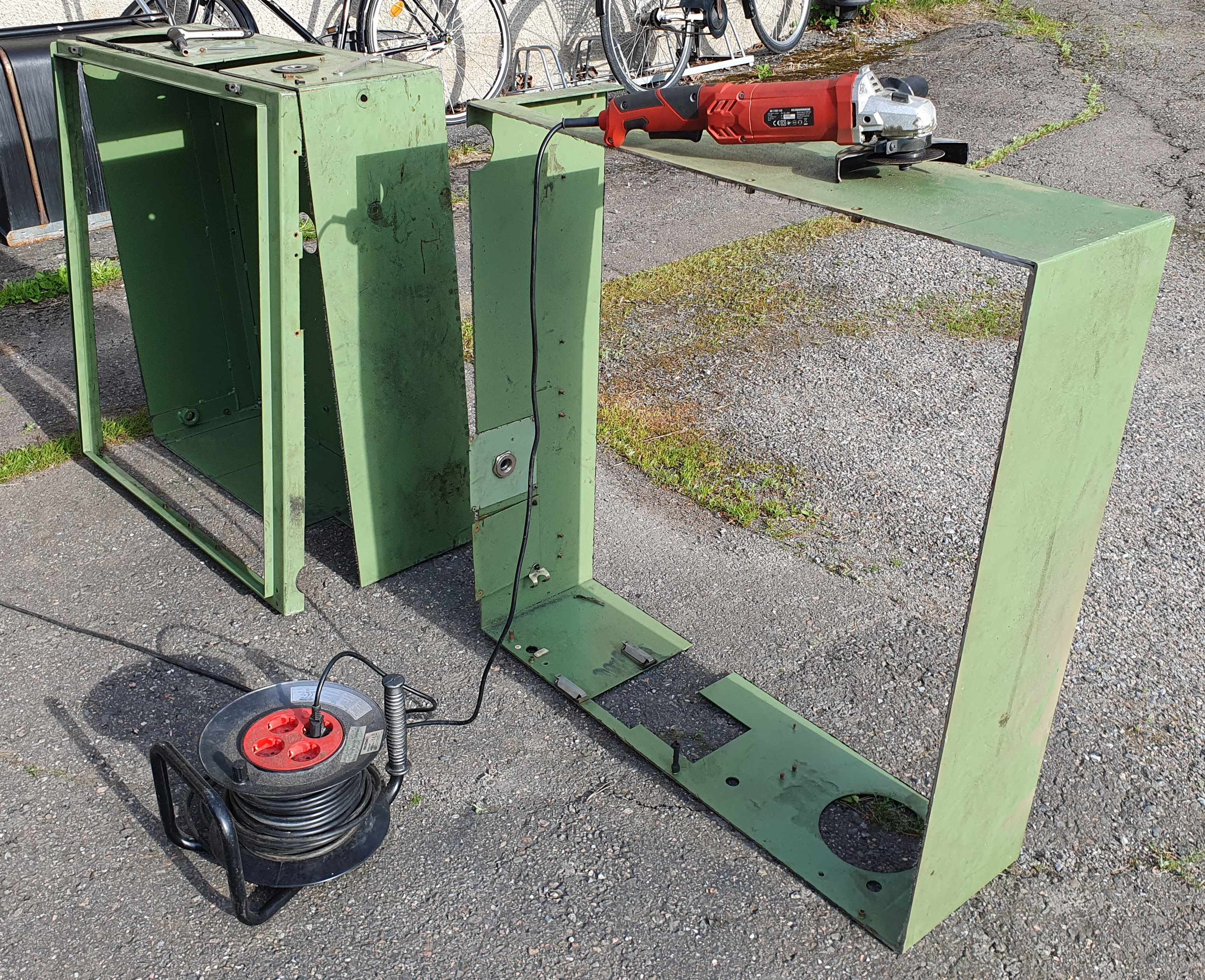
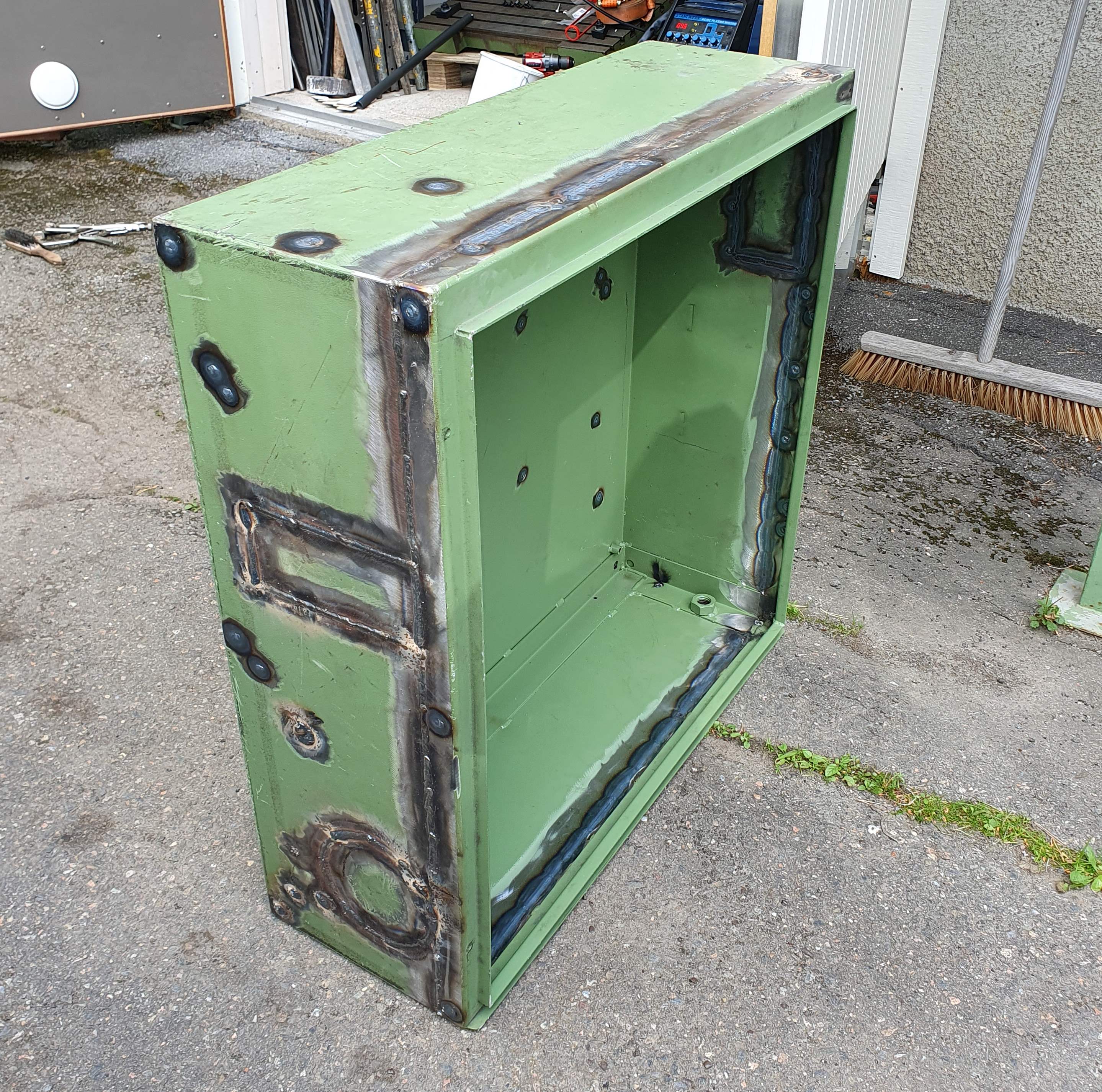
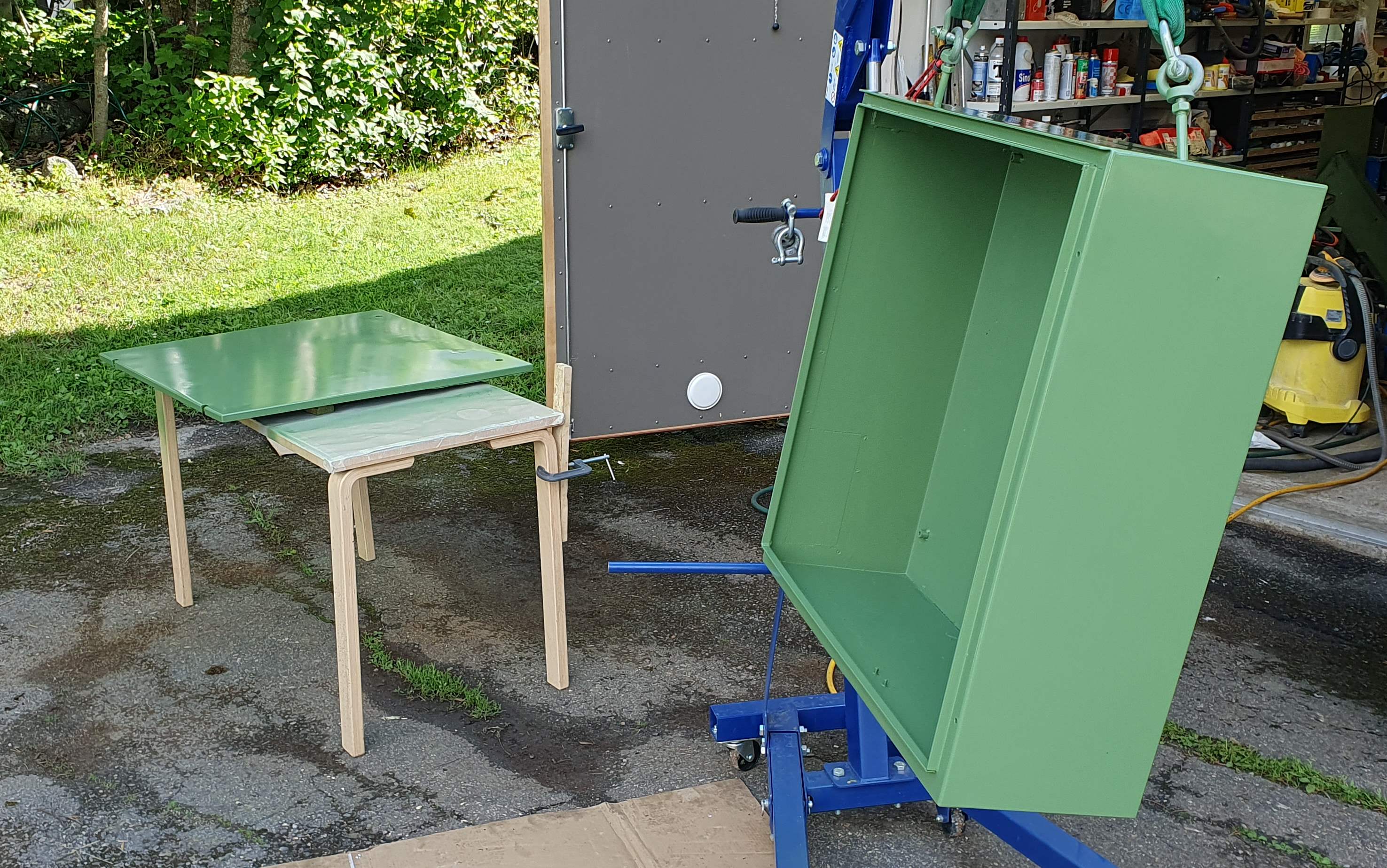
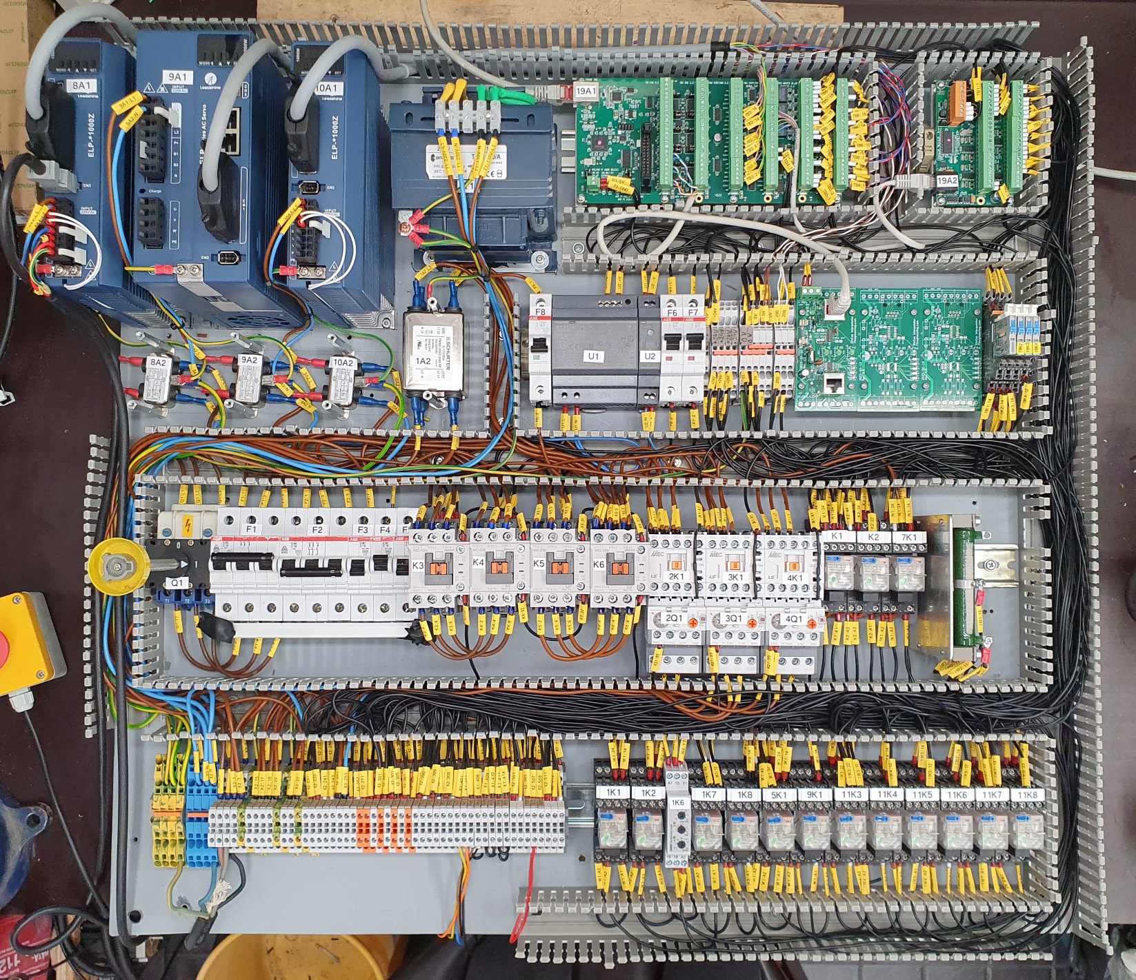
I have worked a bit on the machine as well and started putting it back together. I am not in a situation where I almost need the electrical cabinet before proceeding. For that one I took some inspiration from RotarySMP and cut a section ~25 cm deep out of the cabinet. I will put the mill in a corner, and this will end up saving me a decent amount of space. At the same time, I patched up all of the old holes in it. And with some filler and beautiful Maho green, it starts looking decent again.
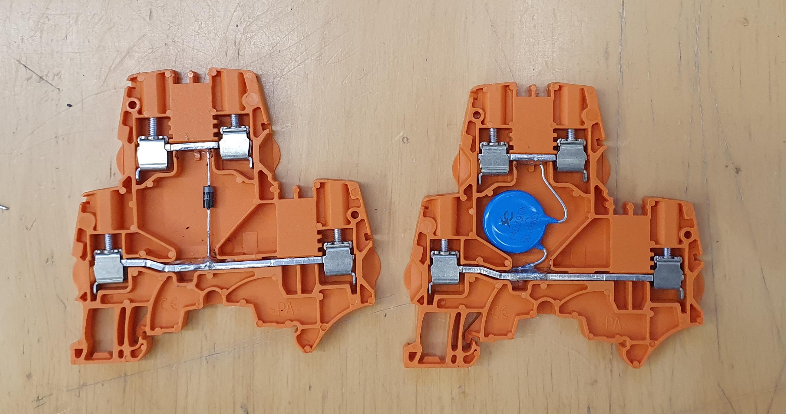
The electrical back plate also starts to be complete, at least for now. The planned wiring is done, but I still need two more SinCos interpolators, and sawing and cable channel covers to length. But regardless of that, the back plate can be installed to the electrical cabinet once that is fastened to the mill. Then external wiring and testing can start for real. I used orange terminal blocks to indicate that they have protection inside. This was a convenient possibility with the two level terminal blocks. For the solenoids, I soldered in diodes (1N4004) and for that gearbox motors I used varistors.
Attachments:
The following user(s) said Thank You: RotarySMP
Please Log in or Create an account to join the conversation.
- Finngineering
- Offline
- Senior Member
-

Less
More
- Posts: 53
- Thank you received: 34
19 Jul 2024 19:32 #305667
by Finngineering
Replied by Finngineering on topic Un-lobotomizing a Maho MH600T
Here is a photo of the back plate. For some reason I was not able to attach it to the previous message.
Offtopic, but is there also a resolution (actually more like width*height) limitation in addition to the 1.6 Mb size limit informed when posting a message to the forums? When I cut the widht*height to half, I could post. But previously it would not allow me to post it even with an image size < 500 kB.
Offtopic, but is there also a resolution (actually more like width*height) limitation in addition to the 1.6 Mb size limit informed when posting a message to the forums? When I cut the widht*height to half, I could post. But previously it would not allow me to post it even with an image size < 500 kB.
Attachments:
The following user(s) said Thank You: RotarySMP, tommylight, besriworld
Please Log in or Create an account to join the conversation.
- RotarySMP
-

- Offline
- Platinum Member
-

Less
More
- Posts: 1542
- Thank you received: 572
26 Jul 2024 11:29 #306070
by RotarySMP
Replied by RotarySMP on topic Un-lobotomizing a Maho MH600T
You made a fantastic job on that cabinet. Respect!
The following user(s) said Thank You: Finngineering
Please Log in or Create an account to join the conversation.
- Finngineering
- Offline
- Senior Member
-

Less
More
- Posts: 53
- Thank you received: 34
20 Sep 2024 07:28 #310499
by Finngineering
Replied by Finngineering on topic Un-lobotomizing a Maho MH600T
A bit more progress.
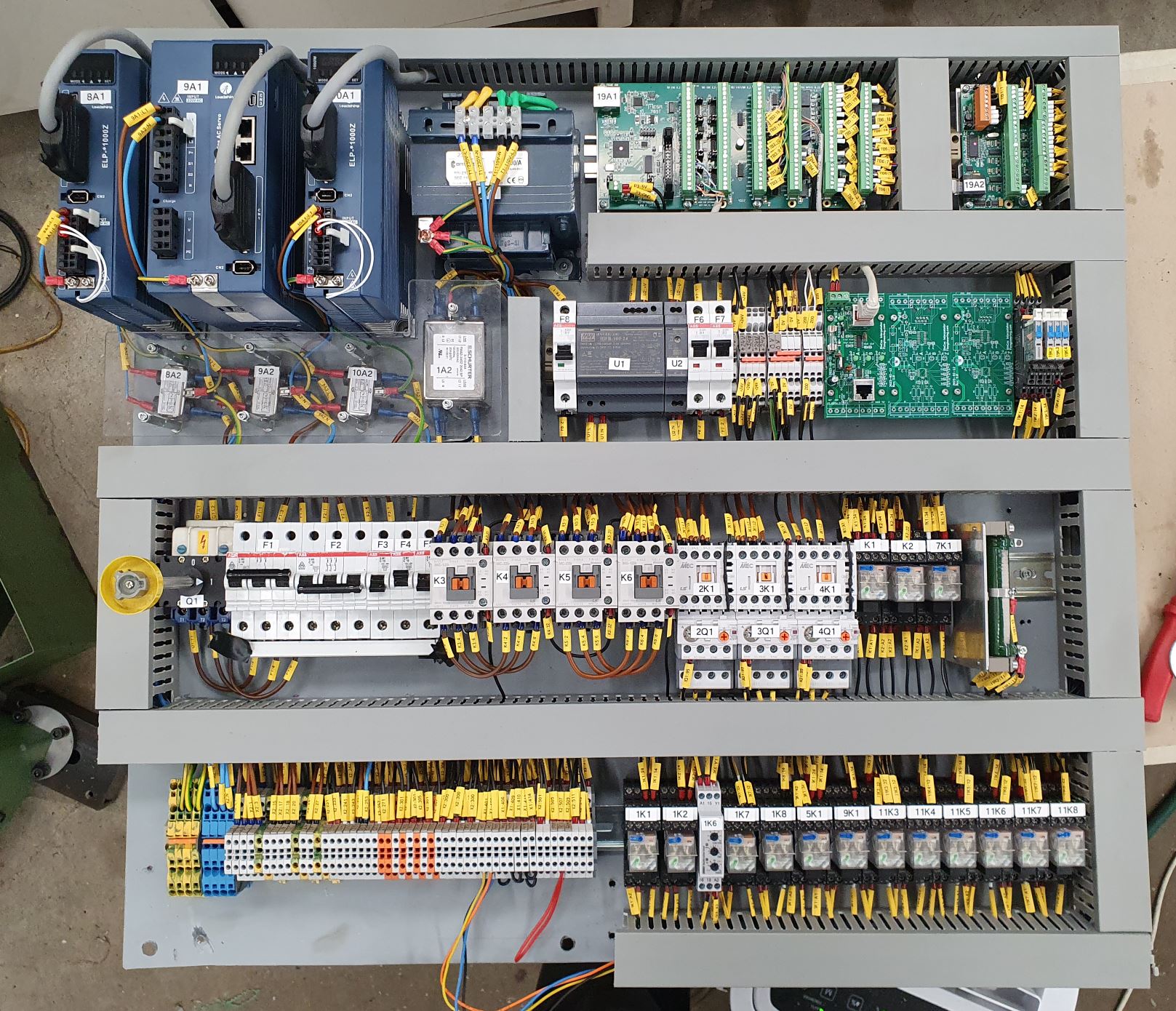
I cut the cable channel covers to length and also the touch protection plate for the filters under the servo drives. This is most likely as nice a photo as I will ever get from the cabinet. From here it's most likely only downhill
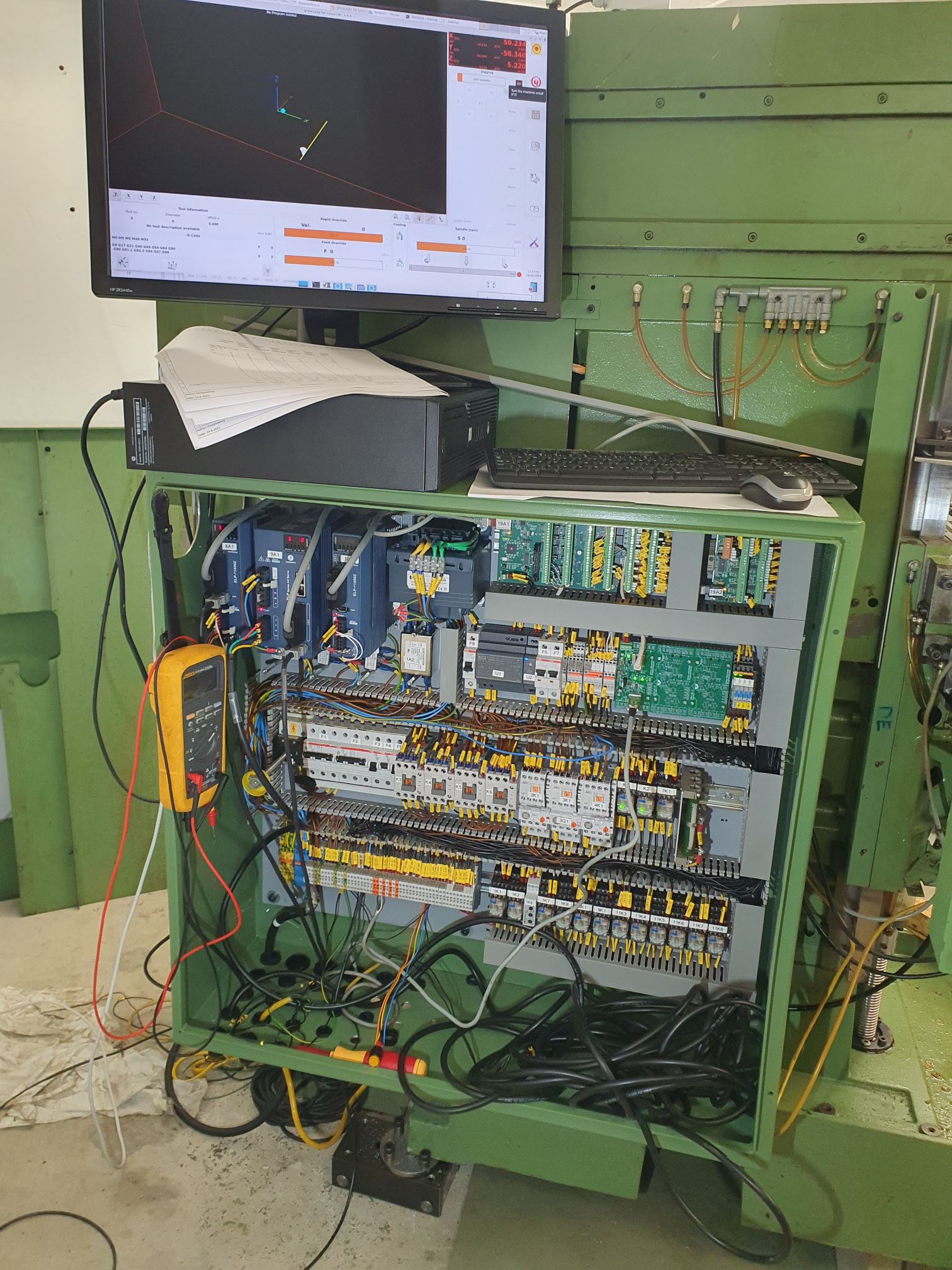
I have put the cabinet on the machine, and started with some preliminary commissioning. The first task is just to get the axes moving so I can adjust the linear scales and end stops (and that doesn't require much else than connecting the servos). Once that is done I will try to do some cable management for all the cables on the machine. Because I moved the electrical cabinet closer to the table, I cannot reuse the original way the cables were routed from the X/Z axes. But also in some other areas, I want to tie the cables down somehow.
Attachments:
The following user(s) said Thank You: RotarySMP, besriworld, Unlogic
Please Log in or Create an account to join the conversation.
Time to create page: 0.228 seconds

