Search Results (Searched for: )
- Gusgus
- Gusgus
18 Sep 2025 19:08
sorry i had a formatting error
Replied by Gusgus on topic Remora - Rpi Software Stepping Using External Microcontroller via SPI
Remora - Rpi Software Stepping Using External Microcontroller via SPI
Category: Computers and Hardware
{
	"Board": "BIGTREETECH Octopus Pro",
	"Modules":[
	{
	"Thread": "Servo",
	"Type": "Reset Pin",
		"Comment":			"Reset pin",
		"Pin":				"PC_15"
	},
		{
	"Thread": "Servo",
	"Type": "eStop",
		"Comment":			"eStop",
		"Pin":				"PG_12"
	},
	{
    "Thread": "Servo",
    "Type": "PWM",
            "Comment":                      "Spindle",
            "SP[i]":                        3,
            "PWM Pin":                      "PB_0",
            "PWM Max":                      255,
            "Hardware PWM":                 "True",
            "Variable Freq":                "True",
            "Period SP[i]":         1,
            "Period us":                    200
    },
	{
	"Thread": "Base",
	"Type": "Stepgen",
		"Comment":			"X - Joint 0 step generator",
		"Joint Number":		0,
		"Step Pin": 		"PF_9",
		"Direction Pin": 	"PF_10",
		"Enable Pin": 		"PG_2"
	},
	{
	"Thread": "Base",
	"Type": "Stepgen",
		"Comment":			"Y1 - Joint 1 step generator",
		"Joint Number":		1,
		"Step Pin": 		"PC_13",
		"Direction Pin": 	"PF_0",
		"Enable Pin": 		"PF_1"
	},
	{
	"Thread": "Base",
	"Type": "Stepgen",
		"Comment":			"Y2 - Joint 1 step generator",
		"Joint Number":		1,
		"Step Pin": 		"PE_2",
		"Direction Pin": 	"PE_3",
		"Enable Pin": 		"PD_4"
	},
	{
	"Thread": "Base",
	"Type": "Stepgen",
		"Comment":			"Z - Joint 2 step generator",
		"Joint Number":		2,
		"Step Pin": 		"PE_6",
		"Direction Pin": 	"PA_14",
		"Enable Pin": 		"PE_0"
	},
	{
	"Thread": "Servo",
	"Type": "Digital Pin",
		"Comment":			"X min",
		"Pin":				"PG_6",
		"Mode":				"Input",
		"Data Bit":			0
	},
	{
	"Thread": "Servo",
	"Type": "Digital Pin",
		"Comment":			"Y min",
		"Pin":				"PG_9",
		"Mode":				"Input",
		"Data Bit":			1
	},
	{
	"Thread": "Servo",
	"Type": "Digital Pin",
		"Comment":			"Z min",
		"Pin":				"PG_10",
		"Mode":				"Input",
		"Data Bit":			2
	},
	{
	"Thread": "Servo",
	"Type": "Digital Pin",
		"Comment":			"Probe",
		"Pin":				"PG_11",
		"Mode":				"Input",
		"Data Bit":			3
	}
	]
}
# Basic LinuxCNC config for testing of Remora firmware

[EMC]
MACHINE = Remora-XYZ
DEBUG = 0
VERSION = 1.1

[DISPLAY]
DISPLAY = axis
EDITOR = gedit
POSITION_OFFSET = RELATIVE
POSITION_FEEDBACK = ACTUAL
ARCDIVISION = 64
GRIDS = 10mm 20mm 50mm 100mm
MAX_FEED_OVERRIDE = 1.2
MIN_SPINDLE_OVERRIDE = 0.5
MAX_SPINDLE_OVERRIDE = 1.2
DEFAULT_LINEAR_VELOCITY = 28.7
MIN_LINEAR_VELOCITY = 0
MAX_LINEAR_VELOCITY = 28.7
DEFAULT_ANGULAR_VELOCITY = 28.7
MIN_ANGULAR_VELOCITY = 0
MAX_ANGULAR_VELOCITY = 28.7
INTRO_GRAPHIC = linuxcnc.gif
INTRO_TIME = 5
PROGRAM_PREFIX = ~/linuxcnc/nc_files
INCREMENTS = 50mm 10mm 5mm 1mm .5mm .1mm .05mm .01mm

[KINS]
JOINTS = 3
#KINEMATICS =trivkins coordinates=XYZ kinstype=BOTH
KINEMATICS =trivkins coordinates=XYZ

[FILTER]
PROGRAM_EXTENSION = .py Python Script
py = python

[TASK]
TASK = milltask
CYCLE_TIME = 0.010

[RS274NGC]
PARAMETER_FILE = linuxcnc.var

[EMCMOT]
EMCMOT = motmod
COMM_TIMEOUT = 1.0
COMM_WAIT = 0.010
BASE_PERIOD = 0
SERVO_PERIOD = 5000000

[HAL]
HALFILE = remora-xyz.hal
POSTGUI_HALFILE = postgui_call_list.hal

[TRAJ]
COORDINATES =  X Y Z
LINEAR_UNITS = mm
ANGULAR_UNITS = degree
CYCLE_TIME = 0.010
DEFAULT_LINEAR_VELOCITY = 4.17
MAX_LINEAR_VELOCITY = 28.7
NO_FORCE_HOMING = 1

[EMCIO]
EMCIO = io
CYCLE_TIME = 0.100
TOOL_TABLE = tool.tbl

#*** AXIS_X *******************************
[AXIS_X]
MAX_VELOCITY = 28.7
MAX_ACCELERATION = 287.0
MIN_LIMIT = -0.001
MAX_LIMIT = 1080.0

[JOINT_0]
TYPE = LINEAR
HOME = 0.0
MIN_LIMIT = -0.001
MAX_LIMIT = 1080.0
MAX_VELOCITY = 28.7
MAX_ACCELERATION = 287.0
STEPGEN_MAXACCEL = 1000.0
SCALE = 100.0
FERROR = 5.0
MIN_FERROR = 5.0
HOME_OFFSET = 0.000000
HOME_SEARCH_VEL = -45.000000
HOME_LATCH_VEL = -2.500000
HOME_SEQUENCE = 1
#******************************************


#*** AXIS_Y *******************************
[AXIS_Y]
MAX_VELOCITY = 28.7
MAX_ACCELERATION = 287.0
MIN_LIMIT = -0.001
MAX_LIMIT = 950.0

[JOINT_1]
TYPE = LINEAR
HOME = 0.0
MIN_LIMIT = -0.001
MAX_LIMIT = 950.0
MAX_VELOCITY = 28.7
MAX_ACCELERATION = 287.0
STEPGEN_MAXACCEL = 1000.0
SCALE = 100.0
FERROR = 5.0
MIN_FERROR = 5.0
HOME_OFFSET = 0.000000
HOME_SEARCH_VEL = -45.000000
HOME_LATCH_VEL = 2.500000
HOME_SEQUENCE = 2
#******************************************


#*** AXIS_Z *******************************
[AXIS_Z]
MAX_VELOCITY = 20.0
MAX_ACCELERATION = 150.0
MIN_LIMIT = -125.0
MAX_LIMIT = 0.001

[JOINT_2]
TYPE = LINEAR
HOME = 0.0
MIN_LIMIT = -125.0
MAX_LIMIT = 0.001
MAX_VELOCITY = 20
MAX_ACCELERATION = 150.0
STEPGEN_MAXACCEL = 187.5
SCALE = 800.0
FERROR = 5.0
MIN_FERROR = 5.0
HOME_OFFSET = 0.000000
HOME_SEARCH_VEL = 15.000000
HOME_LATCH_VEL = 0.625000
HOME_SEQUENCE = 0
#******************************************
sorry i had a formatting error
- souh-hil

18 Sep 2025 19:07
Firmware Request for 7i92 – Plasma CNC Build was created by souh-hil
Firmware Request for 7i92 – Plasma CNC Build
Category: Driver Boards
Hello everyone,This is my first post here on the LinuxCNC forum, and also my very first CNC build — so please forgive any mistakes or lack of experience on my part. I'm doing my best to learn as I go.I'm building a plasma CNC machine and using a Mesa 7i92 card. For my setup, I’ll be connecting two 5-axis breakout boards — one on P1 and one on P2. I’m looking for a suitable firmware that would allow me to:
- Use 4 or 5 encoder inputs (for THCAD and potentially other uses)
- Have at least 10 inputs and 5 outputs for general machine control
- Gusgus
- Gusgus
18 Sep 2025 19:04
Replied by Gusgus on topic Remora - Rpi Software Stepping Using External Microcontroller via SPI
Remora - Rpi Software Stepping Using External Microcontroller via SPI
Category: Computers and Hardware
Hello once again!
I haven't really been active but we got to testing once again and now I have encountered another issue I don't understand.
So now we get movement and stable connection to the octopus, we got an spi cable with shielding and that worked wonders, thank you tommylight for the suggestion and thanks Scotta for all the help.
The issue we are encountering now is that we have x y1 y2 and z, but we only get movement from x and y1, y2 and z are completely unresponsive, we have eliminated the drivers and their wiring since if we connect the y2 and z terminals to the x and y1 outputs on the octopus we get movement from them.
We have them wired to the octopus' Motor 4, 5, 6, and 7 ports, which are decleared in the following config:
We are running this in our .ini file:
and this in our .hal file:

We flashed this firmware to it: github.com/scottalford75/Remora/tree/mai...in/STM32F446/BTT_446
and are running the above mentioned config file.
we also tried looking at the debug info but nothing came up, here's the printout:
All the pins are generated in the correct order it seem's, we are gonna test next the output signal strength, maybe the drivers don't have enough power on high state to start moving, even if everything is connected to the same ground.
I haven't really been active but we got to testing once again and now I have encountered another issue I don't understand.
So now we get movement and stable connection to the octopus, we got an spi cable with shielding and that worked wonders, thank you tommylight for the suggestion and thanks Scotta for all the help.
The issue we are encountering now is that we have x y1 y2 and z, but we only get movement from x and y1, y2 and z are completely unresponsive, we have eliminated the drivers and their wiring since if we connect the y2 and z terminals to the x and y1 outputs on the octopus we get movement from them.
We have them wired to the octopus' Motor 4, 5, 6, and 7 ports, which are decleared in the following config:
[color=#d4d4d4]{[/color][color=#9cdcfe]"Board"[/color][color=#d4d4d4]: [/color][color=#ce9178]"BIGTREETECH Octopus Pro"[/color][color=#d4d4d4],[/color][color=#9cdcfe]"Modules"[/color][color=#d4d4d4]:[[/color][color=#d4d4d4]{[/color][color=#9cdcfe]"Thread"[/color][color=#d4d4d4]: [/color][color=#ce9178]"Servo"[/color][color=#d4d4d4],[/color][color=#9cdcfe]"Type"[/color][color=#d4d4d4]: [/color][color=#ce9178]"Reset Pin"[/color][color=#d4d4d4],[/color][color=#9cdcfe]"Comment"[/color][color=#d4d4d4]: [/color][color=#ce9178]"Reset pin"[/color][color=#d4d4d4],[/color][color=#9cdcfe]"Pin"[/color][color=#d4d4d4]: [/color][color=#ce9178]"PC_15"[/color][color=#d4d4d4]},[/color][color=#d4d4d4]{[/color][color=#9cdcfe]"Thread"[/color][color=#d4d4d4]: [/color][color=#ce9178]"Servo"[/color][color=#d4d4d4],[/color][color=#9cdcfe]"Type"[/color][color=#d4d4d4]: [/color][color=#ce9178]"eStop"[/color][color=#d4d4d4],[/color][color=#9cdcfe]"Comment"[/color][color=#d4d4d4]: [/color][color=#ce9178]"eStop"[/color][color=#d4d4d4],[/color][color=#9cdcfe]"Pin"[/color][color=#d4d4d4]: [/color][color=#ce9178]"PG_12"[/color][color=#d4d4d4]},[/color][color=#d4d4d4]{[/color][color=#9cdcfe]"Thread"[/color][color=#d4d4d4]: [/color][color=#ce9178]"Servo"[/color][color=#d4d4d4],[/color][color=#9cdcfe]"Type"[/color][color=#d4d4d4]: [/color][color=#ce9178]"PWM"[/color][color=#d4d4d4],[/color][color=#9cdcfe]"Comment"[/color][color=#d4d4d4]: [/color][color=#ce9178]"Spindle"[/color][color=#d4d4d4],[/color][color=#9cdcfe]"SP[i]"[/color][color=#d4d4d4]: [/color][color=#b5cea8]3[/color][color=#d4d4d4],[/color][color=#9cdcfe]"PWM Pin"[/color][color=#d4d4d4]: [/color][color=#ce9178]"PB_0"[/color][color=#d4d4d4],[/color][color=#9cdcfe]"PWM Max"[/color][color=#d4d4d4]: [/color][color=#b5cea8]255[/color][color=#d4d4d4],[/color][color=#9cdcfe]"Hardware PWM"[/color][color=#d4d4d4]: [/color][color=#ce9178]"True"[/color][color=#d4d4d4],[/color][color=#9cdcfe]"Variable Freq"[/color][color=#d4d4d4]: [/color][color=#ce9178]"True"[/color][color=#d4d4d4],[/color][color=#9cdcfe]"Period SP[i]"[/color][color=#d4d4d4]: [/color][color=#b5cea8]1[/color][color=#d4d4d4],[/color][color=#9cdcfe]"Period us"[/color][color=#d4d4d4]: [/color][color=#b5cea8]200[/color][color=#d4d4d4]},[/color][color=#d4d4d4]{[/color][color=#9cdcfe]"Thread"[/color][color=#d4d4d4]: [/color][color=#ce9178]"Base"[/color][color=#d4d4d4],[/color][color=#9cdcfe]"Type"[/color][color=#d4d4d4]: [/color][color=#ce9178]"Stepgen"[/color][color=#d4d4d4],[/color][color=#9cdcfe]"Comment"[/color][color=#d4d4d4]: [/color][color=#ce9178]"X - Joint 0 step generator"[/color][color=#d4d4d4],[/color][color=#9cdcfe]"Joint Number"[/color][color=#d4d4d4]: [/color][color=#b5cea8]0[/color][color=#d4d4d4],[/color][color=#9cdcfe]"Step Pin"[/color][color=#d4d4d4]: [/color][color=#ce9178]"PF_9"[/color][color=#d4d4d4],[/color][color=#9cdcfe]"Direction Pin"[/color][color=#d4d4d4]: [/color][color=#ce9178]"PF_10"[/color][color=#d4d4d4],[/color][color=#9cdcfe]"Enable Pin"[/color][color=#d4d4d4]: [/color][color=#ce9178]"PG_2"[/color][color=#d4d4d4]},[/color][color=#d4d4d4]{[/color][color=#9cdcfe]"Thread"[/color][color=#d4d4d4]: [/color][color=#ce9178]"Base"[/color][color=#d4d4d4],[/color][color=#9cdcfe]"Type"[/color][color=#d4d4d4]: [/color][color=#ce9178]"Stepgen"[/color][color=#d4d4d4],[/color][color=#9cdcfe]"Comment"[/color][color=#d4d4d4]: [/color][color=#ce9178]"Y1 - Joint 1 step generator"[/color][color=#d4d4d4],[/color][color=#9cdcfe]"Joint Number"[/color][color=#d4d4d4]: [/color][color=#b5cea8]1[/color][color=#d4d4d4],[/color][color=#9cdcfe]"Step Pin"[/color][color=#d4d4d4]: [/color][color=#ce9178]"PC_13"[/color][color=#d4d4d4],[/color][color=#9cdcfe]"Direction Pin"[/color][color=#d4d4d4]: [/color][color=#ce9178]"PF_0"[/color][color=#d4d4d4],[/color][color=#9cdcfe]"Enable Pin"[/color][color=#d4d4d4]: [/color][color=#ce9178]"PF_1"[/color][color=#d4d4d4]},[/color][color=#d4d4d4]{[/color][color=#9cdcfe]"Thread"[/color][color=#d4d4d4]: [/color][color=#ce9178]"Base"[/color][color=#d4d4d4],[/color][color=#9cdcfe]"Type"[/color][color=#d4d4d4]: [/color][color=#ce9178]"Stepgen"[/color][color=#d4d4d4],[/color][color=#9cdcfe]"Comment"[/color][color=#d4d4d4]: [/color][color=#ce9178]"Y2 - Joint 1 step generator"[/color][color=#d4d4d4],[/color][color=#9cdcfe]"Joint Number"[/color][color=#d4d4d4]: [/color][color=#b5cea8]1[/color][color=#d4d4d4],[/color][color=#9cdcfe]"Step Pin"[/color][color=#d4d4d4]: [/color][color=#ce9178]"PE_2"[/color][color=#d4d4d4],[/color][color=#9cdcfe]"Direction Pin"[/color][color=#d4d4d4]: [/color][color=#ce9178]"PE_3"[/color][color=#d4d4d4],[/color][color=#9cdcfe]"Enable Pin"[/color][color=#d4d4d4]: [/color][color=#ce9178]"PD_4"[/color][color=#d4d4d4]},[/color][color=#d4d4d4]{[/color][color=#9cdcfe]"Thread"[/color][color=#d4d4d4]: [/color][color=#ce9178]"Base"[/color][color=#d4d4d4],[/color][color=#9cdcfe]"Type"[/color][color=#d4d4d4]: [/color][color=#ce9178]"Stepgen"[/color][color=#d4d4d4],[/color][color=#9cdcfe]"Comment"[/color][color=#d4d4d4]: [/color][color=#ce9178]"Z - Joint 2 step generator"[/color][color=#d4d4d4],[/color][color=#9cdcfe]"Joint Number"[/color][color=#d4d4d4]: [/color][color=#b5cea8]2[/color][color=#d4d4d4],[/color][color=#9cdcfe]"Step Pin"[/color][color=#d4d4d4]: [/color][color=#ce9178]"PE_6"[/color][color=#d4d4d4],[/color][color=#9cdcfe]"Direction Pin"[/color][color=#d4d4d4]: [/color][color=#ce9178]"PA_14"[/color][color=#d4d4d4],[/color][color=#9cdcfe]"Enable Pin"[/color][color=#d4d4d4]: [/color][color=#ce9178]"PE_0"[/color][color=#d4d4d4]},[/color][color=#d4d4d4]{[/color][color=#9cdcfe]"Thread"[/color][color=#d4d4d4]: [/color][color=#ce9178]"Servo"[/color][color=#d4d4d4],[/color][color=#9cdcfe]"Type"[/color][color=#d4d4d4]: [/color][color=#ce9178]"Digital Pin"[/color][color=#d4d4d4],[/color][color=#9cdcfe]"Comment"[/color][color=#d4d4d4]: [/color][color=#ce9178]"X min"[/color][color=#d4d4d4],[/color][color=#9cdcfe]"Pin"[/color][color=#d4d4d4]: [/color][color=#ce9178]"PG_6"[/color][color=#d4d4d4],[/color][color=#9cdcfe]"Mode"[/color][color=#d4d4d4]: [/color][color=#ce9178]"Input"[/color][color=#d4d4d4],[/color][color=#9cdcfe]"Data Bit"[/color][color=#d4d4d4]: [/color][color=#b5cea8]0[/color][color=#d4d4d4]},[/color][color=#d4d4d4]{[/color][color=#9cdcfe]"Thread"[/color][color=#d4d4d4]: [/color][color=#ce9178]"Servo"[/color][color=#d4d4d4],[/color][color=#9cdcfe]"Type"[/color][color=#d4d4d4]: [/color][color=#ce9178]"Digital Pin"[/color][color=#d4d4d4],[/color][color=#9cdcfe]"Comment"[/color][color=#d4d4d4]: [/color][color=#ce9178]"Y min"[/color][color=#d4d4d4],[/color][color=#9cdcfe]"Pin"[/color][color=#d4d4d4]: [/color][color=#ce9178]"PG_9"[/color][color=#d4d4d4],[/color][color=#9cdcfe]"Mode"[/color][color=#d4d4d4]: [/color][color=#ce9178]"Input"[/color][color=#d4d4d4],[/color][color=#9cdcfe]"Data Bit"[/color][color=#d4d4d4]: [/color][color=#b5cea8]1[/color][color=#d4d4d4]},[/color][color=#d4d4d4]{[/color][color=#9cdcfe]"Thread"[/color][color=#d4d4d4]: [/color][color=#ce9178]"Servo"[/color][color=#d4d4d4],[/color][color=#9cdcfe]"Type"[/color][color=#d4d4d4]: [/color][color=#ce9178]"Digital Pin"[/color][color=#d4d4d4],[/color][color=#9cdcfe]"Comment"[/color][color=#d4d4d4]: [/color][color=#ce9178]"Z min"[/color][color=#d4d4d4],[/color][color=#9cdcfe]"Pin"[/color][color=#d4d4d4]: [/color][color=#ce9178]"PG_10"[/color][color=#d4d4d4],[/color][color=#9cdcfe]"Mode"[/color][color=#d4d4d4]: [/color][color=#ce9178]"Input"[/color][color=#d4d4d4],[/color][color=#9cdcfe]"Data Bit"[/color][color=#d4d4d4]: [/color][color=#b5cea8]2[/color][color=#d4d4d4]},[/color][color=#d4d4d4]{[/color][color=#9cdcfe]"Thread"[/color][color=#d4d4d4]: [/color][color=#ce9178]"Servo"[/color][color=#d4d4d4],[/color][color=#9cdcfe]"Type"[/color][color=#d4d4d4]: [/color][color=#ce9178]"Digital Pin"[/color][color=#d4d4d4],[/color][color=#9cdcfe]"Comment"[/color][color=#d4d4d4]: [/color][color=#ce9178]"Probe"[/color][color=#d4d4d4],[/color][color=#9cdcfe]"Pin"[/color][color=#d4d4d4]: [/color][color=#ce9178]"PG_11"[/color][color=#d4d4d4],[/color][color=#9cdcfe]"Mode"[/color][color=#d4d4d4]: [/color][color=#ce9178]"Input"[/color][color=#d4d4d4],[/color][color=#9cdcfe]"Data Bit"[/color][color=#d4d4d4]: [/color][color=#b5cea8]3[/color][color=#d4d4d4]}[/color][color=#d4d4d4]][/color][color=#d4d4d4]}[/color]We are running this in our .ini file:
[color=#6a9955]# Basic LinuxCNC config for testing of Remora firmware[/color] [color=#d4d4d4][EMC][/color][color=#569cd6]MACHINE[/color][color=#d4d4d4] = Remora-XYZ[/color][color=#569cd6]DEBUG[/color][color=#d4d4d4] = 0[/color][color=#569cd6]VERSION[/color][color=#d4d4d4] = 1.1[/color] [color=#d4d4d4][DISPLAY][/color][color=#569cd6]DISPLAY[/color][color=#d4d4d4] = axis[/color][color=#569cd6]EDITOR[/color][color=#d4d4d4] = gedit[/color][color=#569cd6]POSITION_OFFSET[/color][color=#d4d4d4] = RELATIVE[/color][color=#569cd6]POSITION_FEEDBACK[/color][color=#d4d4d4] = ACTUAL[/color][color=#569cd6]ARCDIVISION[/color][color=#d4d4d4] = 64[/color][color=#569cd6]GRIDS[/color][color=#d4d4d4] = 10mm 20mm 50mm 100mm[/color][color=#569cd6]MAX_FEED_OVERRIDE[/color][color=#d4d4d4] = 1.2[/color][color=#569cd6]MIN_SPINDLE_OVERRIDE[/color][color=#d4d4d4] = 0.5[/color][color=#569cd6]MAX_SPINDLE_OVERRIDE[/color][color=#d4d4d4] = 1.2[/color][color=#569cd6]DEFAULT_LINEAR_VELOCITY[/color][color=#d4d4d4] = 28.7[/color][color=#569cd6]MIN_LINEAR_VELOCITY[/color][color=#d4d4d4] = 0[/color][color=#569cd6]MAX_LINEAR_VELOCITY[/color][color=#d4d4d4] = 28.7[/color][color=#569cd6]DEFAULT_ANGULAR_VELOCITY[/color][color=#d4d4d4] = 28.7[/color][color=#569cd6]MIN_ANGULAR_VELOCITY[/color][color=#d4d4d4] = 0[/color][color=#569cd6]MAX_ANGULAR_VELOCITY[/color][color=#d4d4d4] = 28.7[/color][color=#569cd6]INTRO_GRAPHIC[/color][color=#d4d4d4] = linuxcnc.gif[/color][color=#569cd6]INTRO_TIME[/color][color=#d4d4d4] = 5[/color][color=#569cd6]PROGRAM_PREFIX[/color][color=#d4d4d4] = ~/linuxcnc/nc_files[/color][color=#569cd6]INCREMENTS[/color][color=#d4d4d4] = 50mm 10mm 5mm 1mm .5mm .1mm .05mm .01mm[/color] [color=#d4d4d4][KINS][/color][color=#569cd6]JOINTS[/color][color=#d4d4d4] = 3[/color][color=#6a9955]#KINEMATICS =trivkins coordinates=XYZ kinstype=BOTH[/color][color=#569cd6]KINEMATICS[/color][color=#d4d4d4] =trivkins [/color][color=#569cd6]coordinates[/color][color=#d4d4d4]=XYZ[/color] [color=#d4d4d4][FILTER][/color][color=#569cd6]PROGRAM_EXTENSION[/color][color=#d4d4d4] = .py Python Script[/color][color=#569cd6]py[/color][color=#d4d4d4] = python[/color] [color=#d4d4d4][TASK][/color][color=#569cd6]TASK[/color][color=#d4d4d4] = milltask[/color][color=#569cd6]CYCLE_TIME[/color][color=#d4d4d4] = 0.010[/color] [color=#d4d4d4][RS274NGC][/color][color=#569cd6]PARAMETER_FILE[/color][color=#d4d4d4] = linuxcnc.var[/color] [color=#d4d4d4][EMCMOT][/color][color=#569cd6]EMCMOT[/color][color=#d4d4d4] = motmod[/color][color=#569cd6]COMM_TIMEOUT[/color][color=#d4d4d4] = 1.0[/color][color=#569cd6]COMM_WAIT[/color][color=#d4d4d4] = 0.010[/color][color=#569cd6]BASE_PERIOD[/color][color=#d4d4d4] = 0[/color][color=#569cd6]SERVO_PERIOD[/color][color=#d4d4d4] = 5000000[/color] [color=#d4d4d4][HAL][/color][color=#569cd6]HALFILE[/color][color=#d4d4d4] = remora-xyz.hal[/color][color=#569cd6]POSTGUI_HALFILE[/color][color=#d4d4d4] = postgui_call_list.hal[/color] [color=#d4d4d4][TRAJ][/color][color=#569cd6]COORDINATES[/color][color=#d4d4d4] = X Y Z [/color][color=#569cd6]LINEAR_UNITS[/color][color=#d4d4d4] = mm[/color][color=#569cd6]ANGULAR_UNITS[/color][color=#d4d4d4] = degree[/color][color=#569cd6]CYCLE_TIME[/color][color=#d4d4d4] = 0.010[/color][color=#569cd6]DEFAULT_LINEAR_VELOCITY[/color][color=#d4d4d4] = 4.17[/color][color=#569cd6]MAX_LINEAR_VELOCITY[/color][color=#d4d4d4] = 28.7[/color][color=#569cd6]NO_FORCE_HOMING[/color][color=#d4d4d4] = 1 [/color] [color=#d4d4d4][EMCIO][/color][color=#569cd6]EMCIO[/color][color=#d4d4d4] = io[/color][color=#569cd6]CYCLE_TIME[/color][color=#d4d4d4] = 0.100[/color][color=#569cd6]TOOL_TABLE[/color][color=#d4d4d4] = tool.tbl[/color] [color=#6a9955]#*** AXIS_X *******************************[/color][color=#d4d4d4][AXIS_X][/color][color=#569cd6]MAX_VELOCITY[/color][color=#d4d4d4] = 28.7[/color][color=#569cd6]MAX_ACCELERATION[/color][color=#d4d4d4] = 287.0[/color][color=#569cd6]MIN_LIMIT[/color][color=#d4d4d4] = -0.001[/color][color=#569cd6]MAX_LIMIT[/color][color=#d4d4d4] = 1080.0[/color] [color=#d4d4d4][JOINT_0][/color][color=#569cd6]TYPE[/color][color=#d4d4d4] = LINEAR[/color][color=#569cd6]HOME[/color][color=#d4d4d4] = 0.0[/color][color=#569cd6]MIN_LIMIT[/color][color=#d4d4d4] = -0.001[/color][color=#569cd6]MAX_LIMIT[/color][color=#d4d4d4] = 1080.0[/color][color=#569cd6]MAX_VELOCITY[/color][color=#d4d4d4] = 28.7[/color][color=#569cd6]MAX_ACCELERATION[/color][color=#d4d4d4] = 287.0[/color][color=#569cd6]STEPGEN_MAXACCEL[/color][color=#d4d4d4] = 1000.0[/color][color=#569cd6]SCALE[/color][color=#d4d4d4] = 100.0[/color][color=#569cd6]FERROR[/color][color=#d4d4d4] = 5.0[/color][color=#569cd6]MIN_FERROR[/color][color=#d4d4d4] = 5.0[/color][color=#569cd6]HOME_OFFSET[/color][color=#d4d4d4] = 0.000000[/color][color=#569cd6]HOME_SEARCH_VEL[/color][color=#d4d4d4] = -45.000000[/color][color=#569cd6]HOME_LATCH_VEL[/color][color=#d4d4d4] = -2.500000[/color][color=#569cd6]HOME_SEQUENCE[/color][color=#d4d4d4] = 1[/color][color=#6a9955]#******************************************[/color] [color=#6a9955]#*** AXIS_Y *******************************[/color][color=#d4d4d4][AXIS_Y][/color][color=#569cd6]MAX_VELOCITY[/color][color=#d4d4d4] = 28.7[/color][color=#569cd6]MAX_ACCELERATION[/color][color=#d4d4d4] = 287.0[/color][color=#569cd6]MIN_LIMIT[/color][color=#d4d4d4] = -0.001[/color][color=#569cd6]MAX_LIMIT[/color][color=#d4d4d4] = 950.0[/color] [color=#d4d4d4][JOINT_1][/color][color=#569cd6]TYPE[/color][color=#d4d4d4] = LINEAR[/color][color=#569cd6]HOME[/color][color=#d4d4d4] = 0.0[/color][color=#569cd6]MIN_LIMIT[/color][color=#d4d4d4] = -0.001[/color][color=#569cd6]MAX_LIMIT[/color][color=#d4d4d4] = 950.0[/color][color=#569cd6]MAX_VELOCITY[/color][color=#d4d4d4] = 28.7[/color][color=#569cd6]MAX_ACCELERATION[/color][color=#d4d4d4] = 287.0[/color][color=#569cd6]STEPGEN_MAXACCEL[/color][color=#d4d4d4] = 1000.0[/color][color=#569cd6]SCALE[/color][color=#d4d4d4] = 100.0[/color][color=#569cd6]FERROR[/color][color=#d4d4d4] = 5.0[/color][color=#569cd6]MIN_FERROR[/color][color=#d4d4d4] = 5.0[/color][color=#569cd6]HOME_OFFSET[/color][color=#d4d4d4] = 0.000000[/color][color=#569cd6]HOME_SEARCH_VEL[/color][color=#d4d4d4] = -45.000000[/color][color=#569cd6]HOME_LATCH_VEL[/color][color=#d4d4d4] = 2.500000[/color][color=#569cd6]HOME_SEQUENCE[/color][color=#d4d4d4] = 2[/color][color=#6a9955]#******************************************[/color] [color=#6a9955]#*** AXIS_Z *******************************[/color][color=#d4d4d4][AXIS_Z][/color][color=#569cd6]MAX_VELOCITY[/color][color=#d4d4d4] = 20.0[/color][color=#569cd6]MAX_ACCELERATION[/color][color=#d4d4d4] = 150.0[/color][color=#569cd6]MIN_LIMIT[/color][color=#d4d4d4] = -125.0[/color][color=#569cd6]MAX_LIMIT[/color][color=#d4d4d4] = 0.001[/color] [color=#d4d4d4][JOINT_2][/color][color=#569cd6]TYPE[/color][color=#d4d4d4] = LINEAR[/color][color=#569cd6]HOME[/color][color=#d4d4d4] = 0.0[/color][color=#569cd6]MIN_LIMIT[/color][color=#d4d4d4] = -125.0[/color][color=#569cd6]MAX_LIMIT[/color][color=#d4d4d4] = 0.001[/color][color=#569cd6]MAX_VELOCITY[/color][color=#d4d4d4] = 20[/color][color=#569cd6]MAX_ACCELERATION[/color][color=#d4d4d4] = 150.0[/color][color=#569cd6]STEPGEN_MAXACCEL[/color][color=#d4d4d4] = 187.5[/color][color=#569cd6]SCALE[/color][color=#d4d4d4] = 800.0[/color][color=#569cd6]FERROR[/color][color=#d4d4d4] = 5.0[/color][color=#569cd6]MIN_FERROR[/color][color=#d4d4d4] = 5.0[/color][color=#569cd6]HOME_OFFSET[/color][color=#d4d4d4] = 0.000000[/color][color=#569cd6]HOME_SEARCH_VEL[/color][color=#d4d4d4] = 15.000000[/color][color=#569cd6]HOME_LATCH_VEL[/color][color=#d4d4d4] = 0.625000[/color][color=#569cd6]HOME_SEQUENCE[/color][color=#d4d4d4] = 0[/color][color=#6a9955]#******************************************[/color]
and this in our .hal file:
# load the realtime components

    loadrt [KINS]KINEMATICS
    loadrt [EMCMOT]EMCMOT base_period_nsec=[EMCMOT]BASE_PERIOD servo_period_nsec=[EMCMOT]SERVO_PERIOD num_joints=[KINS]JOINTS

    loadrt remora-spi SPI_num=0 CS_num=0 SPI_freq=2000000
    #loadrt remora_lpc chip_type=LPC SPI_clk_div=64


# estop loopback, SPI comms enable and feedback
    net user-enable-out     <= iocontrol.0.user-enable-out        => remora.SPI-enable
    net user-request-enable <= iocontrol.0.user-request-enable    => remora.SPI-reset
    net remora-status     <= remora.SPI-status             => iocontrol.0.emc-enable-in


# add the remora and motion functions to threads

    addf remora.read servo-thread
    addf motion-command-handler servo-thread
    addf motion-controller servo-thread
    addf remora.update-freq servo-thread
    addf remora.write servo-thread


# Joint 0 setup

    setp remora.joint.0.scale         [JOINT_0]SCALE
    setp remora.joint.0.maxaccel     [JOINT_0]STEPGEN_MAXACCEL

    net xpos-cmd         <= joint.0.motor-pos-cmd     => remora.joint.0.pos-cmd
    net j0pos-fb         <= remora.joint.0.pos-fb     => joint.0.motor-pos-fb
    net j0enable         <= joint.0.amp-enable-out     => remora.joint.0.enable


# Joint 1 setup

    setp remora.joint.1.scale         [JOINT_1]SCALE
    setp remora.joint.1.maxaccel     [JOINT_1]STEPGEN_MAXACCEL

    net j1pos-cmd         <= joint.1.motor-pos-cmd     => remora.joint.1.pos-cmd
    net j1pos-fb         <= remora.joint.1.pos-fb     => joint.1.motor-pos-fb
    net j1enable         <= joint.1.amp-enable-out     => remora.joint.1.enable


# Joint 2 setup

    setp remora.joint.2.scale         [JOINT_2]SCALE
    setp remora.joint.2.maxaccel     [JOINT_2]STEPGEN_MAXACCEL

    net j2pos-cmd         <= joint.2.motor-pos-cmd     => remora.joint.2.pos-cmd
    net j2pos-fb         <= remora.joint.2.pos-fb     => joint.2.motor-pos-fb
    net j2enable         <= joint.2.amp-enable-out     => remora.joint.2.enable

# inputs
    #endstops
    net X-min remora.input.01 => joint.0.home-sw-in
    net Y-min remora.input.00 => joint.1.home-sw-in
    net Z-min remora.input.02 => joint.2.home-sw-in
We flashed this firmware to it: github.com/scottalford75/Remora/tree/mai...in/STM32F446/BTT_446
and are running the above mentioned config file.
we also tried looking at the debug info but nothing came up, here's the printout:
Creating a std module

Remora PRU - Programmable Realtime Unit

 Mbed-OS6

 Remora-spi Driver

## Entering SETUP state
1. Reading json configuration file
Mounting the filesystem... OK
Opening "/fs/config.txt"... OK
Json config file lenght = 1996
Closing "/fs/config.txt"...
2. Setting up DMA and threads
Initialising SPI1 slave
Initialising DMA for SPI

3. Parsing json configuration file
Config deserialisation - Deserialization succeeded

4. Config threads
Creating thread 40000
Creating thread 1000
Creating thread 57600

5. Loading modules

Servo thread object
Reset pin
Make Reset Pin at pin PC_15

Creating a std module
Creating Pin @
  port = GPIOC
  pin = 15

Servo thread object
eStop
Make eStop at pin PG_12

Creating a std module
Creating Pin @
  port = GPIOG
  pin = 12

Servo thread object
Spindle
Make PWM at pin PB_0

Creating a std module
Creating variable frequency Hardware PWM at pin PB_0
Creating Pin @
  port = GPIOB
  pin = 0

Base thread object
X - Joint 0 step generator

Creating a std module
Creating Pin @
  port = GPIOG
  pin = 2
Creating Pin @
  port = GPIOF
  pin = 9
Creating Pin @
  port = GPIOF
  pin = 10

Base thread object
Y1 - Joint 1 step generator

Creating a std module
Creating Pin @
  port = GPIOF
  pin = 1
Creating Pin @
  port = GPIOC
  pin = 13
Creating Pin @
  port = GPIOF
  pin = 0

Base thread object
Y2 - Joint 1 step generator

Creating a std module
Creating Pin @
  port = GPIOD
  pin = 4
Creating Pin @
  port = GPIOE
  pin = 2
Creating Pin @
  port = GPIOE
  pin = 3

Base thread object
Z - Joint 2 step generator

Creating a std module
Creating Pin @
  port = GPIOE
  pin = 0
Creating Pin @
  port = GPIOE
  pin = 6
Creating Pin @
  port = GPIOA
  pin = 14

Servo thread object
X min
Make Digital Input at pin PG_6

Creating a std module
  Setting pin as No Pull
Creating Pin @
  port = GPIOG
  pin = 6

Servo thread object
Y min
Make Digital Input at pin PG_9

Creating a std module
  Setting pin as No Pull
Creating Pin @
  port = GPIOG
  pin = 9

Servo thread object
Z min
Make Digital Input at pin PG_10

Creating a std module
  Setting pin as No Pull
Creating Pin @
  port = GPIOG
  pin = 10

Servo thread object
Probe
Make Digital Input at pin PG_11

Creating a std module
  Setting pin as No Pull
Creating Pin @
  port = GPIOG
  pin = 11

## Entering START state

Starting the BASE thread
Registering interrupt for interrupt number = 24
        power on Timer 9

Starting the SERVO thread
Registering interrupt for interrupt number = 25
        power on Timer 10

## Entering IDLE state

## Entering RUNNING state

## Entering RESET state
   Resetting rxBuffer

## Entering IDLE state
All the pins are generated in the correct order it seem's, we are gonna test next the output signal strength, maybe the drivers don't have enough power on high state to start moving, even if everything is connected to the same ground.
- unknown
- unknown
18 Sep 2025 19:02
Replied by unknown on topic 7i76E Spindle configuration
7i76E Spindle configuration
Category: PnCConf Wizard
When you make a config the only changes are made in the linuxcnc/configs directory in your home folder.
No changes are made to any system files, none at all. So it doesn't matter how bad a config is made it does not affect anything outside of the above mentioned directory.
PCW is a very patient member of the forum and the guy that runs Mesa Electronics. This is the first time I have show any frustration with a forum member. Ever.
When you have an issue, with anything in this world, diagnosis follows a process. Whilst it may not make sense to you, it does to those offering advice. To go off do something that is unnecessary and you have been advised not is deeply disrespectful and can quite possibly throw a spanner in the works and bring you back to where you started. Eventually people may come to the conclusion that trying to help is not worth their.
The best course of action would be to go back and follow PCE's advice to the letter, do not skip a step.
For a second time does your spindle controller require an analogue voltage, or does it require a PWM signal. Actually it may be an idea to qualify what controller you are using and any documents pertaining to the spindle controller.
- meister
- meister
18 Sep 2025 18:46
Replied by meister on topic Charge Pump
Charge Pump
Category: General LinuxCNC Questions
I've thought about it for a long time and think I've found a pretty good solution.easy, cheap, rocksolid, no mcu, no IC
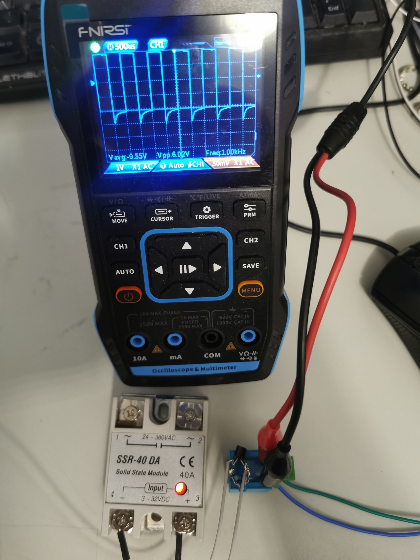
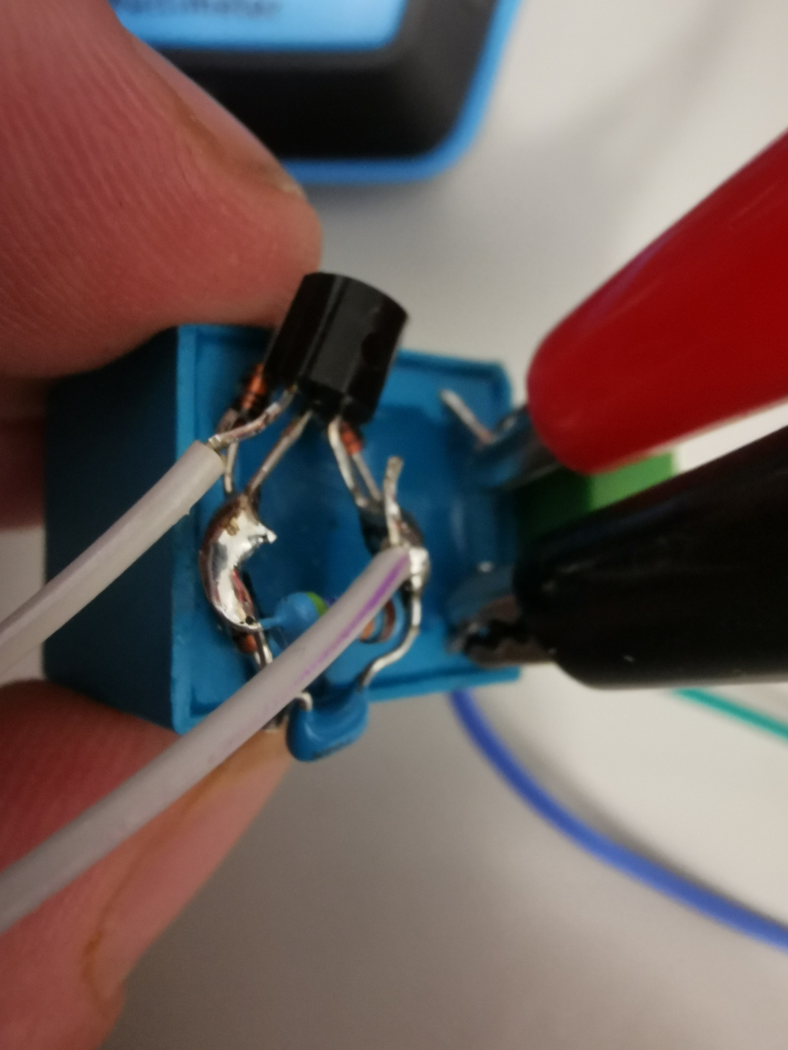
signal -> nf-transformer -> rectifier -> transistor (+resistor and capacitor) -> Relais/SSR
signal -> nf-transformer -> rectifier -> transistor (+resistor and capacitor) -> Relais/SSR
- amanker
- amanker
18 Sep 2025 18:42
Replied by amanker on topic Remora - Rpi Software Stepping Using External Microcontroller via SPI
Remora - Rpi Software Stepping Using External Microcontroller via SPI
Category: Computers and Hardware
Finally I got it working. I shortened the spi cables, reduced spi frequency, tried erasing and flashing remora via stm32cube, nothing worked. But after some time it automagically started working. I don't know how it worked?
- RobotMatic

18 Sep 2025 17:51 - 18 Sep 2025 17:52
Replied by RobotMatic on topic 7i76E Spindle configuration
7i76E Spindle configuration
Category: PnCConf Wizard
- RobotMatic
18 Sep 2025 17:44 - 18 Sep 2025 17:50
Replied by RobotMatic on topic 7i76E Spindle configuration
7i76E Spindle configuration
Category: PnCConf Wizard
- andronick83
18 Sep 2025 16:49 - 18 Sep 2025 16:50
Replied by andronick83 on topic automatic initialization of the axis interface in full screen
automatic initialization of the axis interface in full screen
Category: General LinuxCNC Questions
In the latest linuxcnc also works:
root_window.attributes('-zoomed', True)
root_window.attributes('-zoomed', True)
- RobotMatic
18 Sep 2025 15:07
Replied by RobotMatic on topic 7i76E Spindle configuration
7i76E Spindle configuration
Category: PnCConf Wizard
PCW :I am very sorry about this and I thank you immensely.I did everything I could to understand you.I wanted to make sure I had a clean installation to eliminate my doubts.Thank You.!!!!!
- PCW

18 Sep 2025 14:11
Replied by PCW on topic 7i76E Spindle configuration
7i76E Spindle configuration
Category: PnCConf Wizard
Changing the OS/LinuxCNC version is a complete waste of time.
This is most likely a hardware or hal file setup issue.
I explained how to debug this issue, but was ignored, I'm out.
This is most likely a hardware or hal file setup issue.
I explained how to debug this issue, but was ignored, I'm out.
- djones@burketruck.com
- djones@burketruck.com
18 Sep 2025 12:33
Any Fiber Laser Successes? was created by djones@burketruck.com
Any Fiber Laser Successes?
Category: Plasma & Laser
We were at fabtech last week and were shocked at how affordable (in relation to 5 years ago) fiber lasers have gotten, especially the imported chinese ones. One thing that I noticed is that all of the decent chinese ones used Max Photonics laser head & source. We all know the imported chinese lasers can vary on quality, reliability, and parts/service.
So that led to the question: Why not buy an older name brand CO2 laser (mazak, amada, bystronic, etc...) and retrofit it with LinuxCNC, new servos & drives, and a Max Fiber laser source and head? A lot of places are practically giving away older CO2 lasers that work just fine, which would be a perfect starter. That way it is a better built machine with modern controls and laser, for most likely less money than a chinese import laser.
Has anyone successfully done this yet? We did a Mazak VTC mill earlier this year and are absolutely thrilled with how it turned out running Probe Basic.
- rbobey1989

18 Sep 2025 11:37
Ethercat HDT LOVATO Servodrives was created by rbobey1989
Ethercat HDT LOVATO Servodrives
Category: General LinuxCNC Questions
Hi guys,
I've been looking for decent servo drives for DC motors with a nominal current of 10A and a peak current of 20A for some time now.
A while ago, I also started using Beckhoff modules with Linuxcnc+Ethercat, which made me happy because it was relatively easy to get up and running.
I've been looking at the Beckhoff EL7342+ZB8610 package, which reaches 6.5A per channel, which is relatively good for small DC motors, although the price is steep.
I've used HDT LOVATO's Colibri series servo amplifiers in the past; they're relatively easy to use, offering differential analog and PWM/DIR control. What has caught my attention is that they have developed other quite versatile DX, TMC and NTT series of servo drives under various field buses CanOpen, ModBus, ****Ethercat**** etc, which can be configured to handle different types of brushless motors, permanent magnet DC motors, three-phase asynchronous motors etc, the type of feedback to use is also configurable: incremental encoder, absolute SSI, BISS, Endat2.2. Another thing I liked is that they have a software called Caliper that can be downloaded from the official HDT LOVATO website. It allows you to configure these drivers. The documentation is quite good. Although the documentation is available in several languages, there is some inconsistency on the website, and only the Italian manuals are correct.
After some waiting and many emails, I contacted HDT LOVATO and ordered the DGFox60EVO-10/20 driver. This can be controlled via analog control, pulse/dir, and ***Ethercat***. These drivers are developed in compliance with the CIA402 standard. So, I think I'll start reading a little about the PDO descriptions of these servo drivers to develop a driver that I can incorporate into Linuxcnc. It's always good to have your input, so good ideas are welcome.
The servodrive manuals and PDO descriptions can be downloaded from the HDT LOVATO website . You must create an account to download the documentation.
I'm looking forward to the servodrive's arrival. Greetings to everyone.
- unknown
- unknown
18 Sep 2025 10:49
Replied by unknown on topic Python pendant logic problems
Python pendant logic problems
Category: General LinuxCNC Questions
I'm probably missing the point, but how are the signals connecting to the internal Linuxcnc signals ?
Look this is an example of a MPG setup using the parallel port but it illustrates some basic routing of hal signals.
Look this is an example of a MPG setup using the parallel port but it illustrates some basic routing of hal signals.
- RobotMatic
18 Sep 2025 10:15 - 18 Sep 2025 17:46
Replied by RobotMatic on topic 7i76E Spindle configuration
7i76E Spindle configuration
Category: PnCConf Wizard
I performed a fresh installation of the entire system.
I updated everything.
configure the wired network connection to the motherboard and check with the PING command
using the wizard I created the configuration 7i76e (it did not allow me to configure TB4)
- Linux 6.1.0-39 rt
- Linuxcnc 2.9.5
- New config Pncconfig wizard
I updated everything.
configure the wired network connection to the motherboard and check with the PING command
using the wizard I created the configuration 7i76e (it did not allow me to configure TB4)
- Linux 6.1.0-39 rt
- Linuxcnc 2.9.5
- New config Pncconfig wizard
Time to create page: 2.438 seconds