Z axis - Can I use this with PlasmaC and Mesa 7i76e?
- txtrone
-
 Topic Author
- Offline
- Platinum Member
-

Less
More
- Posts: 384
- Thank you received: 106
11 Jan 2021 20:42 #194951
by txtrone
Z axis - Can I use this with PlasmaC and Mesa 7i76e? was created by txtrone
I am nearing the end of my base machine setup, the Z axis. I have a 'Super Z' which is made by another manufacturer, which I am sure most people here are familiar with.
My question is sort of broad, but in a nutshell: Can I make the 'Super Z' work with my 7i76e card and PlasmaC without modification?
OR
Would I be better off to start from scratch on the Z axis?
Thanks
My question is sort of broad, but in a nutshell: Can I make the 'Super Z' work with my 7i76e card and PlasmaC without modification?
OR
Would I be better off to start from scratch on the Z axis?
Thanks
Please Log in or Create an account to join the conversation.
- rodw
-

- Offline
- Platinum Member
-
Less
More
- Posts: 11967
- Thank you received: 4078
11 Jan 2021 21:14 #194958
by rodw
Replied by rodw on topic Z axis - Can I use this with PlasmaC and Mesa 7i76e?
My Z axis took me 3 months!
I think I'd try to make it work.
It says it is for 12 volt and normally we use 24 volts. But 12v field power is OK (and more susceptible to noise)
I think if you gut the electronics and wired the sensors yourself (replacing if necessary for 24V) it would not be too bad to sort out.
I am aware of a gantry circuit board coming mid Feb that has a DB15 connector for all X & Z home and limit switches including breakaways and a 5V power supply for a laser pointer which might make this type of retrofit fairly easy. You can PM me on Plasmaspider if you would like to know more.
The following user(s) said Thank You: txtrone
Please Log in or Create an account to join the conversation.
- txtrone
-
Topic Author
- Offline
- Platinum Member
-
Less
More
- Posts: 384
- Thank you received: 106
11 Jan 2021 21:19 #194959
by txtrone
You think I should start off with a 12v to get it working? Could always switch to 24v later.
I will PM you now on the other forum.
Replied by txtrone on topic Z axis - Can I use this with PlasmaC and Mesa 7i76e?
My Z axis took me 3 months!
I think I'd try to make it work.
It says it is for 12 volt and normally we use 24 volts. But 12v field power is OK (and more susceptible to noise)
I think if you gut the electronics and wired the sensors yourself (replacing if necessary for 24V) it would not be too bad to sort out.
I am aware of a gantry circuit board coming mid Feb that has a DB15 connector for all X & Z home and limit switches including breakaways and a 5V power supply for a laser pointer which might make this type of retrofit fairly easy. You can PM me on Plasmaspider if you would like to know more.
You think I should start off with a 12v to get it working? Could always switch to 24v later.
I will PM you now on the other forum.
Please Log in or Create an account to join the conversation.
- txtrone
-
Topic Author
- Offline
- Platinum Member
-
Less
More
- Posts: 384
- Thank you received: 106
12 Jan 2021 14:36 #195057
by txtrone
Replied by txtrone on topic Z axis - Can I use this with PlasmaC and Mesa 7i76e?
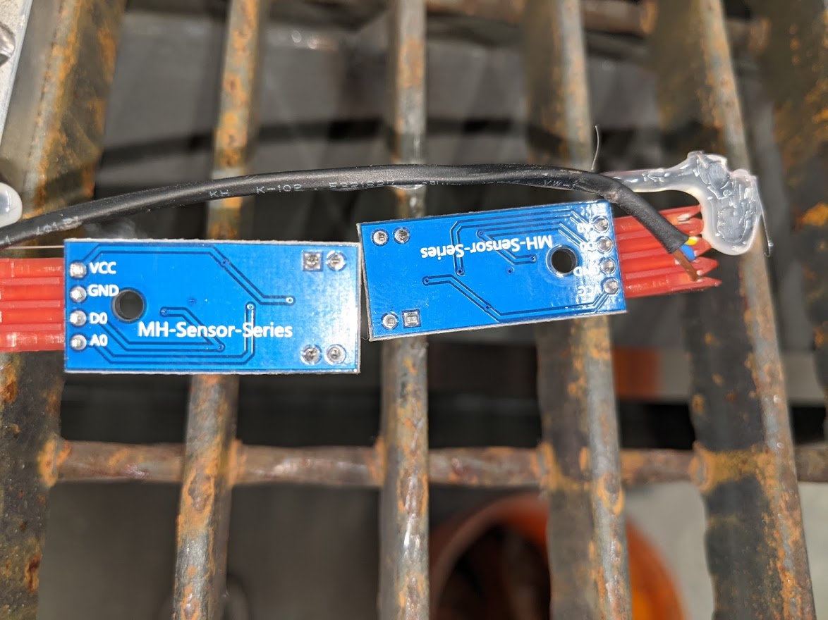
See the photos attached, I don't know which sensor is considered 'optical' .... it looks like two proximity sensors for the Z home and Z float, then (maybe optical) is for the breakaway?? Anyhow, just for now ... could this be wired in directly using a 12vdc psu for those sensors AND still make use of THCAD?
I have many extra wires running from the cabinet up to the Z axis on the gantry... if that helps out.
- OR -
 Would I best off to find some 24V proximity sensors for this application and rebuild?
I have many extra wires running from the cabinet up to the Z axis on the gantry... if that helps out.
- OR -
Please Log in or Create an account to join the conversation.
- andypugh
-

- Offline
- Moderator
-

Less
More
- Posts: 19863
- Thank you received: 4636
12 Jan 2021 14:46 #195058
by andypugh
Replied by andypugh on topic Z axis - Can I use this with PlasmaC and Mesa 7i76e?
There are two optical sensors on the PCBs and what is probably a proximity sensor on the metal plate.
See if you can find a part number on the prox. It is probably good to 32V.
Similarly with the optos on the boards. See what the little chip is, and what supply tolerance it has. And, also the opto sensors. They might be OK with 24V.
The sensor boards look very generic. www.ebay.co.uk/itm/322198737844
Those use an LM393 which is OK to 36V:
www.ti.com/lit/ds/symlink/lm393-n.pdf?ts...Fwww.google.com%252F
I would be tempted to buy a few of the eBay ones to test at 24V. They might need some resistors changing for the higher voltage.
The following user(s) said Thank You: txtrone
Please Log in or Create an account to join the conversation.
- txtrone
-
Topic Author
- Offline
- Platinum Member
-
Less
More
- Posts: 384
- Thank you received: 106
12 Jan 2021 15:08 #195061
by txtrone
Replied by txtrone on topic Z axis - Can I use this with PlasmaC and Mesa 7i76e?
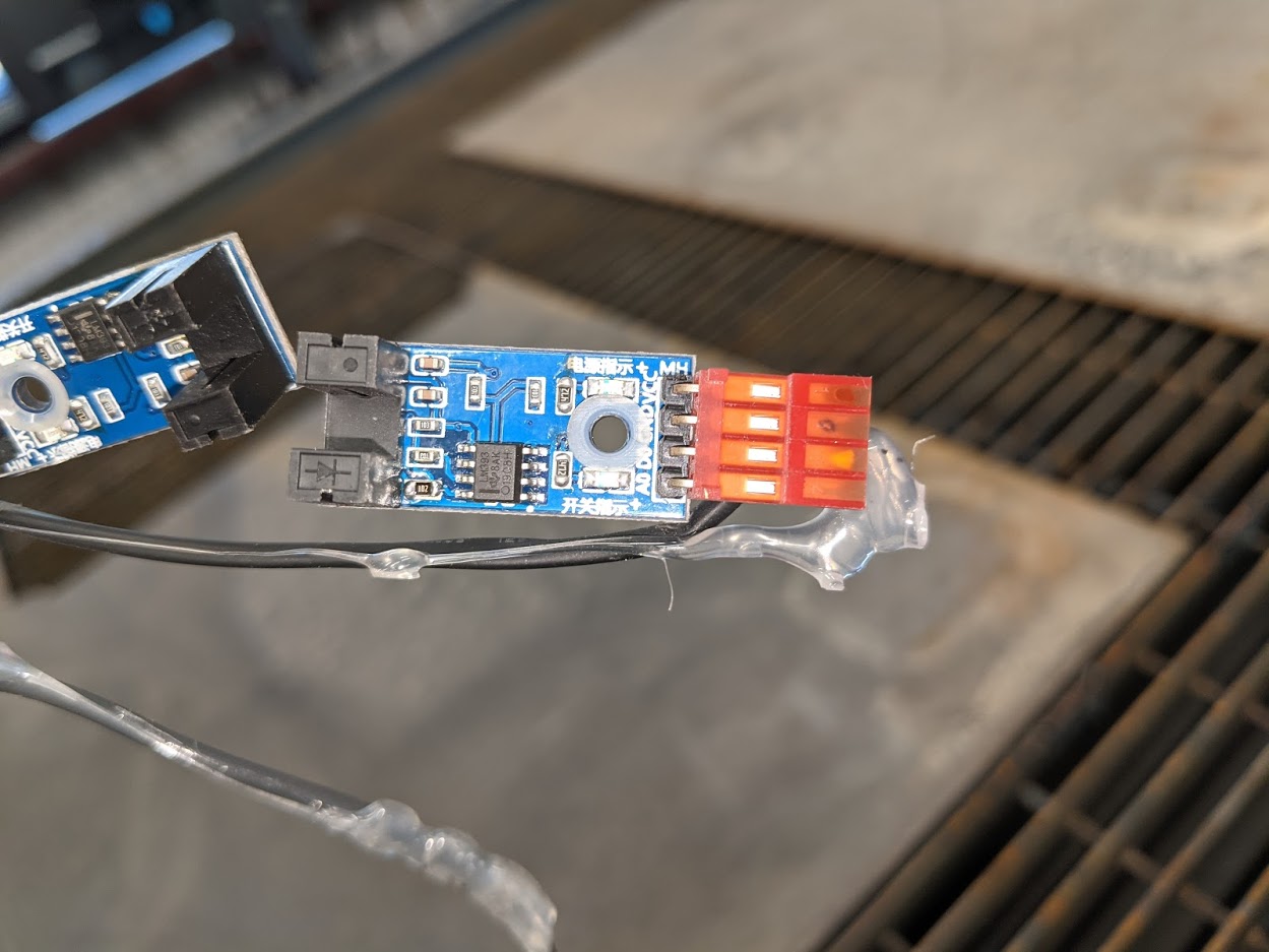
I got it further apart. I can not find any identifying info on the proximity sensor (the one with the target/bullseye symbol on it) the opticals did have some markings.
Please Log in or Create an account to join the conversation.
- txtrone
-
Topic Author
- Offline
- Platinum Member
-
Less
More
- Posts: 384
- Thank you received: 106
12 Jan 2021 15:14 #195063
by txtrone
Replied by txtrone on topic Z axis - Can I use this with PlasmaC and Mesa 7i76e?
Please Log in or Create an account to join the conversation.
- andypugh
-
- Offline
- Moderator
-
Less
More
- Posts: 19863
- Thank you received: 4636
12 Jan 2021 15:22 #195065
by andypugh
Replied by andypugh on topic Z axis - Can I use this with PlasmaC and Mesa 7i76e?
The prox looks like a chape clone of uk.rs-online.com/web/p/proximity-sensors/3395402/
And those are happy to 30V
And those are happy to 30V
Please Log in or Create an account to join the conversation.
- andypugh
-
- Offline
- Moderator
-
Less
More
- Posts: 19863
- Thank you received: 4636
12 Jan 2021 15:25 #195066
by andypugh
That's a completely different style of sensor board.
LM393 is just the comparator chip on the board. The data sheet that I linked earlier shows that those are happy to 36V.
The little PCBs that they assemble in China are designed for 5V operation, but that is just set by the size of the current limiting resistors that they use. The major components will be fine at 24V.
In fact all the components _might_ be OK at 24V, but the LEDs will glow a bit brightly and have shorter lives.
Replied by andypugh on topic Z axis - Can I use this with PlasmaC and Mesa 7i76e?
I believe this is the optical sensor model... which is 5vdc.
www.mysensors.org/build/light-lm393
That's a completely different style of sensor board.
LM393 is just the comparator chip on the board. The data sheet that I linked earlier shows that those are happy to 36V.
The little PCBs that they assemble in China are designed for 5V operation, but that is just set by the size of the current limiting resistors that they use. The major components will be fine at 24V.
In fact all the components _might_ be OK at 24V, but the LEDs will glow a bit brightly and have shorter lives.
The following user(s) said Thank You: txtrone
Please Log in or Create an account to join the conversation.
- andypugh
-
- Offline
- Moderator
-
Less
More
- Posts: 19863
- Thank you received: 4636
12 Jan 2021 15:29 #195068
by andypugh
Replied by andypugh on topic Z axis - Can I use this with PlasmaC and Mesa 7i76e?
Looking more carefully, I would hazard a guess that the sensor boards are 5V eBay parts with a resistor or two swapped by hand. The end resistor adjacent to the Opto emitter looks to have been hand-soldered.
The following user(s) said Thank You: txtrone
Please Log in or Create an account to join the conversation.
Moderators: snowgoer540
Time to create page: 1.589 seconds