Z axis - Can I use this with PlasmaC and Mesa 7i76e?
- andypugh
-

- Offline
- Moderator
-

Less
More
- Posts: 19863
- Thank you received: 4636
12 Jan 2021 23:50 #195152
by andypugh
Replied by andypugh on topic Z axis - Can I use this with PlasmaC and Mesa 7i76e?
It will just prove that the sensor works. (and will confirm that AO and DO are analog and digital outputs)
The following user(s) said Thank You: txtrone
Please Log in or Create an account to join the conversation.
- txtrone
-
 Topic Author
- Offline
- Platinum Member
-

Less
More
- Posts: 384
- Thank you received: 106
16 Jan 2021 00:33 #195501
by txtrone
Replied by txtrone on topic Z axis - Can I use this with PlasmaC and Mesa 7i76e?
Ok, sorry it took me so long... things are crazy at work. When I reconnected the sensors to the wire harness and powered them up nothing happened. The amperage went up on my variable power supply... but not the voltage. I took the sensors back off the wire harness and they worked, at least the LED lights came back on. What would cause that?
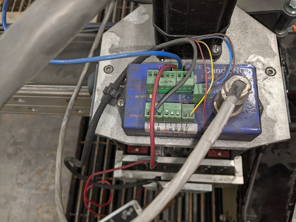
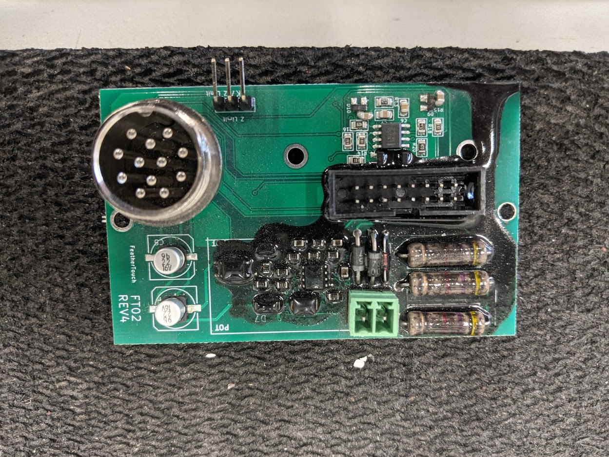
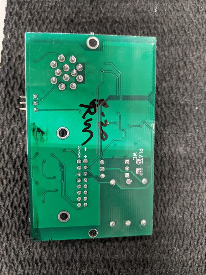
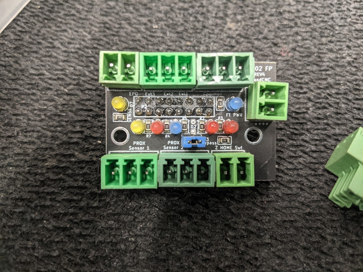
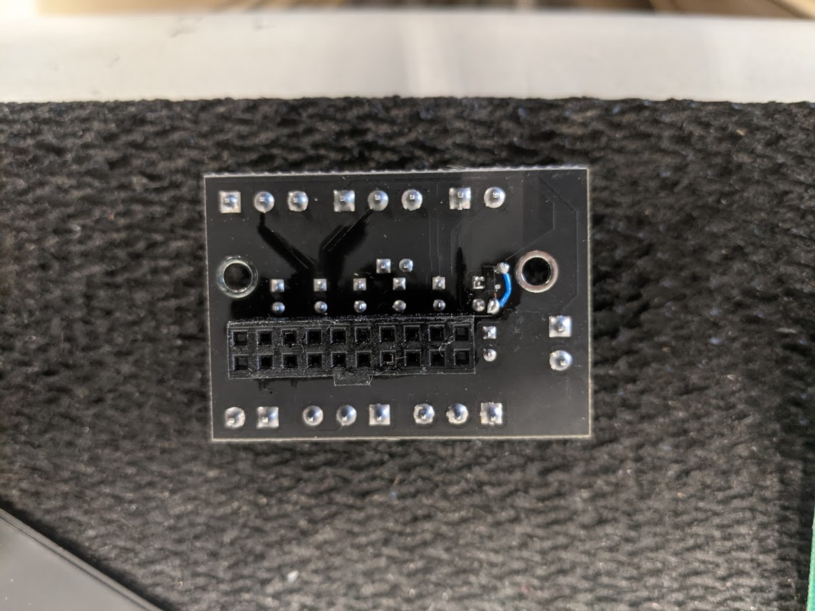
Anyhow, since the little optical sensors and the proximity sensor can handle 24vdc I figured why not hook everything back up to the 'hub' and do some testing. Poof. White smoke. One of the boards fried. These photos show the burnt board and the smaller board that plugged into the top of it.
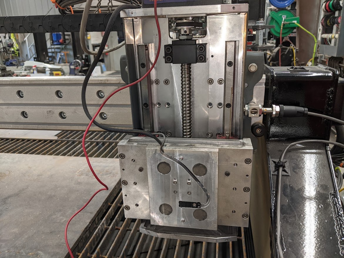
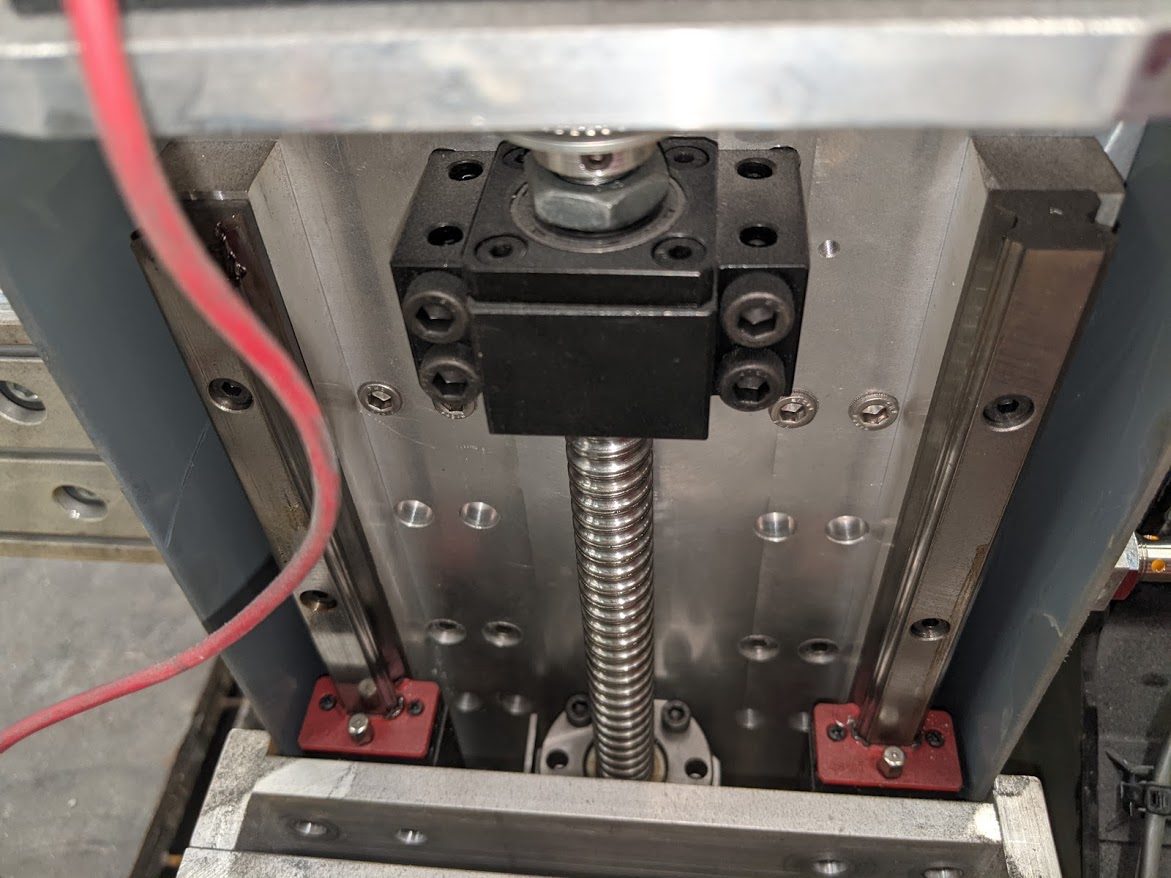
Now, this leaves me with the sensors that can handle 24vdc and a dozen sensor wires that run up to the top of the z from the cabinet where the Mesa 7i76e resides. I have two THCAD modules. Can I make this work with what I have? Or do I need to modify the z axis for different sensors?

Anyhow, since the little optical sensors and the proximity sensor can handle 24vdc I figured why not hook everything back up to the 'hub' and do some testing. Poof. White smoke. One of the boards fried. These photos show the burnt board and the smaller board that plugged into the top of it.
Now, this leaves me with the sensors that can handle 24vdc and a dozen sensor wires that run up to the top of the z from the cabinet where the Mesa 7i76e resides. I have two THCAD modules. Can I make this work with what I have? Or do I need to modify the z axis for different sensors?
Please Log in or Create an account to join the conversation.
- tommylight
-

- Offline
- Moderator
-
Less
More
- Posts: 21661
- Thank you received: 7400
16 Jan 2021 01:24 #195507
by tommylight
Since you do have a lab supply, as an example when testing such a sensor, say it should use 15mA, set the current to 15mA then power on.
I have no idea what those modules do as i can not read the markings on the chips, besides having some LED's and some power resistors.
Replied by tommylight on topic Z axis - Can I use this with PlasmaC and Mesa 7i76e?
That is the definition of a short .... or a reverse voltage applied to a semiconductor.The amperage went up on my variable power supply... but not the voltage.
Since you do have a lab supply, as an example when testing such a sensor, say it should use 15mA, set the current to 15mA then power on.
I have no idea what those modules do as i can not read the markings on the chips, besides having some LED's and some power resistors.
The following user(s) said Thank You: txtrone
Please Log in or Create an account to join the conversation.
- txtrone
-
Topic Author
- Offline
- Platinum Member
-
Less
More
- Posts: 384
- Thank you received: 106
16 Jan 2021 02:04 #195511
by txtrone
Replied by txtrone on topic Z axis - Can I use this with PlasmaC and Mesa 7i76e?
Yeah, that was boneheaded on my part. I could easily buy a replacement, but I don't want to spend any more with that particular manufacturer. I want to learn how to make the z axis work, either with the sensors that are on it... or from scratch.
Please Log in or Create an account to join the conversation.
- andypugh
-
- Offline
- Moderator
-
Less
More
- Posts: 19863
- Thank you received: 4636
16 Jan 2021 23:44 #195594
by andypugh
Replied by andypugh on topic Z axis - Can I use this with PlasmaC and Mesa 7i76e?
The board doesn't look burned to me, that black looks like some kind of resin / sealer. I have no idea why they would do that. though.
The following user(s) said Thank You: txtrone
Please Log in or Create an account to join the conversation.
- PCW
-

- Offline
- Moderator
-
Less
More
- Posts: 17931
- Thank you received: 5255
17 Jan 2021 00:08 #195603
by PCW
Replied by PCW on topic Z axis - Can I use this with PlasmaC and Mesa 7i76e?
Plasma makes all kinds of conductive dust...
The following user(s) said Thank You: txtrone
Please Log in or Create an account to join the conversation.
- txtrone
-
Topic Author
- Offline
- Platinum Member
-
Less
More
- Posts: 384
- Thank you received: 106
17 Jan 2021 02:06 #195623
by txtrone
I give you my word that it burned As soon as I turned on the 24vdc power supply in the cabinet, all of the smoke in FT-02 module came out. D'oh! Oh well, I didn't like that board anyways. heh
Any idea why the two sensors power up on 24vdc individually, but when tied together (in the wire harness) the do not? I am just wondering if the custom discrete components on those boards are setup in a way that will not allow them to function properly without the rest of the puzzle, which is now burned.
I did buy 5ea of those same sensors ($8.19USD) from Amazon. It would be great if I could make them work since my Z is already setup for them.
Replied by txtrone on topic Z axis - Can I use this with PlasmaC and Mesa 7i76e?
The board doesn't look burned to me, that black looks like some kind of resin / sealer. I have no idea why they would do that. though.
I give you my word that it burned
As soon as I turned on the 24vdc power supply in the cabinet, all of the smoke in FT-02 module came out. D'oh! Oh well, I didn't like that board anyways. hehAny idea why the two sensors power up on 24vdc individually, but when tied together (in the wire harness) the do not? I am just wondering if the custom discrete components on those boards are setup in a way that will not allow them to function properly without the rest of the puzzle, which is now burned.
I did buy 5ea of those same sensors ($8.19USD) from Amazon. It would be great if I could make them work since my Z is already setup for them.
Please Log in or Create an account to join the conversation.
- rodw
-

- Offline
- Platinum Member
-
Less
More
- Posts: 11967
- Thank you received: 4078
17 Jan 2021 03:45 #195631
by rodw
Replied by rodw on topic Z axis - Can I use this with PlasmaC and Mesa 7i76e?
Well that made some decisions for you!
I know of a good replacement board coming but its a few weeks away. It uses a DB15 connector and includes a 5V step down power supply (from 24 volts) for a laser pointer. I think there will be a matching case for it too. Its based on what I did for the Spaceship Z axis becasue making all the Z axis connections really was not enjoyable!
I know of a good replacement board coming but its a few weeks away. It uses a DB15 connector and includes a 5V step down power supply (from 24 volts) for a laser pointer. I think there will be a matching case for it too. Its based on what I did for the Spaceship Z axis becasue making all the Z axis connections really was not enjoyable!
The following user(s) said Thank You: txtrone
Please Log in or Create an account to join the conversation.
- txtrone
-
Topic Author
- Offline
- Platinum Member
-
Less
More
- Posts: 384
- Thank you received: 106
17 Jan 2021 04:43 #195633
by txtrone
Just emailed you. I am very interested in this replacement.
In the meantime, I have extra unused 5v, 12v, and 24v power supplies, 2ea THCAD10 units, voltage divider cable for my HT85 (will be here on Tuesday), along with a hoard of other electronic parts... and I have a dozen wires from my z back to my cabinet already installed. I just need to figure out how to make it all work.
Replied by txtrone on topic Z axis - Can I use this with PlasmaC and Mesa 7i76e?
I know of a good replacement board coming but its a few weeks away. It uses a DB15 connector and includes a 5V step down power supply (from 24 volts) for a laser pointer. I think there will be a matching case for it too. Its based on what I did for the Spaceship Z axis becasue making all the Z axis connections really was not enjoyable!
Just emailed you. I am very interested in this replacement.
In the meantime, I have extra unused 5v, 12v, and 24v power supplies, 2ea THCAD10 units, voltage divider cable for my HT85 (will be here on Tuesday), along with a hoard of other electronic parts... and I have a dozen wires from my z back to my cabinet already installed. I just need to figure out how to make it all work.
The following user(s) said Thank You: rodw
Please Log in or Create an account to join the conversation.
- andypugh
-
- Offline
- Moderator
-
Less
More
- Posts: 19863
- Thank you received: 4636
18 Jan 2021 01:15 #195735
by andypugh
One (unlikely) possibility is that the 50mA (or so) that they take is overloading the supply.
Replied by andypugh on topic Z axis - Can I use this with PlasmaC and Mesa 7i76e?
Any idea why the two sensors power up on 24vdc individually, but when tied together (in the wire harness) the do not?
One (unlikely) possibility is that the 50mA (or so) that they take is overloading the supply.
The following user(s) said Thank You: txtrone
Please Log in or Create an account to join the conversation.
Moderators: snowgoer540
Time to create page: 0.632 seconds