Z axis - Can I use this with PlasmaC and Mesa 7i76e?
- txtrone
-
 Topic Author
- Offline
- Platinum Member
-

- Posts: 384
- Thank you received: 106
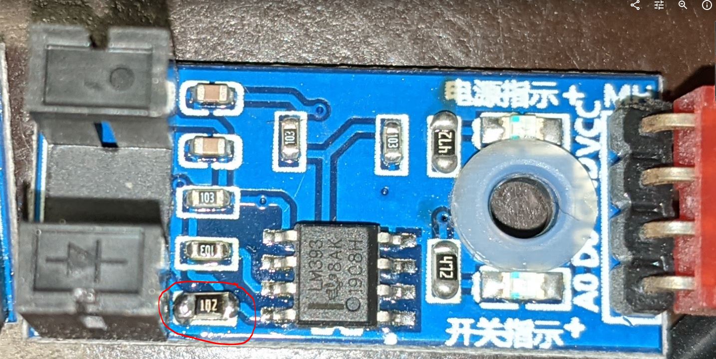
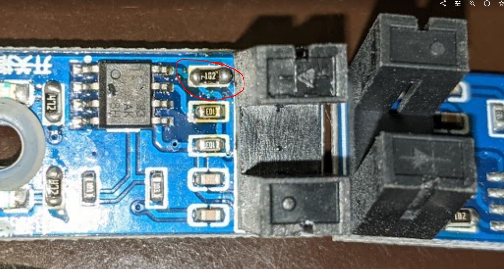
Looking more carefully, I would hazard a guess that the sensor boards are 5V eBay parts with a resistor or two swapped by hand. The end resistor adjacent to the Opto emitter looks to have been hand-soldered.
Are you referring to the resistors I have circled in red?
Please Log in or Create an account to join the conversation.
- andypugh
-

- Offline
- Moderator
-

- Posts: 19863
- Thank you received: 4636
The 102 (1k) is to limit the current through the LED in the sensor. (12v / 1000 = 12mA). The eBay version I linked to had 180R (181) resistors there for a 30mA current (which seems high). This seems to suggest that you can leave that resistor as-is.
Taking a random example from the RS catalogue (uk.rs-online.com/web/p/slotted-optical-switches/1690523/) shows that it is happy up to 50mA LED current. At 24V you would be driving it at half that.
The 4k7 resistors are (probably) the current limiters for the two indicator LEDs. 24V / 4k7 = 5mA. I doubt that many LEDs would be troubled by 5mA. (And, can you even see them when the unit is assembled anyway?)
Given that replacements are easy to source, I would test at 12V from a lab PSU and slowly increase to 24V whilst watching the current draw.
Please Log in or Create an account to join the conversation.
- txtrone
-
Topic Author
- Offline
- Platinum Member
-
- Posts: 384
- Thank you received: 106
Given that replacements are easy to source, I would test at 12V from a lab PSU and slowly increase to 24V whilst watching the current draw.
Will do! I ordered these from Amazon, should be here tomorrow. www.amazon.com/gp/product/B0776RHKB1/ref...00_s00?ie=UTF8&psc=1
Which resistors would I want to replace, and with what value, to make these work with 24 volt for sure? I have a local electronics store right down the way.
The led lights are sort of visible, more of a 'cool' factor I suppose. If they are not necessary then I do not care.
Thanks! This has been very helpful!
A couple of other questions, very noobish.
1) Is this goop that was used to semi seal these boards and wire into the z car most likely everyday run-of-the-mill silicone? Or something more specialized?
2) Are these sensors digital or analog outputs?
Please Log in or Create an account to join the conversation.
- andypugh
-
- Offline
- Moderator
-
- Posts: 19863
- Thank you received: 4636
Which resistors would I want to replace, and with what value, to make these work with 24 volt for sure? I have a local electronics store right down the way.
I would expect there to be a potential divider to provide a reference voltage for the comparator. That should stay the same.
Then a pull-up for the opto output, again that can probably stay the same.
The LED current limiters look to me like they might already be for 24V operation. You can see 181 for the sensor and 102 for the indicators. Your board has each of them approximately 5x bigger. If they were originally 5V boards, now they are 25V boards.
1) Is this goop that was used to semi seal these boards and wire into the z car most likely everyday run-of-the-mill silicone? Or something more specialized?
Obviously I can't feel it from here, but it looks like hot-melt glue to me.
2) Are these sensors digital or analog outputs?
I would guess both, there are pins marked DO (Digital Out?) and AO (Analogue Out?). There would be no need for the LM293 if there wasn't a digital output.
Please Log in or Create an account to join the conversation.
- txtrone
-
Topic Author
- Offline
- Platinum Member
-
- Posts: 384
- Thank you received: 106
")
I will give it a go at 24V now.

Please Log in or Create an account to join the conversation.
- rodw
-

- Offline
- Platinum Member
-
- Posts: 11967
- Thank you received: 4078
Prox sensors have standard wiring colours (blue -, brown + , black output) so they would be easy to rewire.
Please Log in or Create an account to join the conversation.
- txtrone
-
Topic Author
- Offline
- Platinum Member
-
- Posts: 384
- Thank you received: 106
You guys are powering!. I think I would have powered the Super Z up and checked the voltage at VCC and GND. BUt Andy seems to have nailed it all.
Prox sensors have standard wiring colours (blue -, brown + , black output) so they would be easy to rewire.
I forgot to add this last photo, it works (as Andy said it would) at 25vdc. At this point could I incorporate THCAD into this? Should I use the electronic 'box' or 'hub' that is on my Z or should I do away with that?
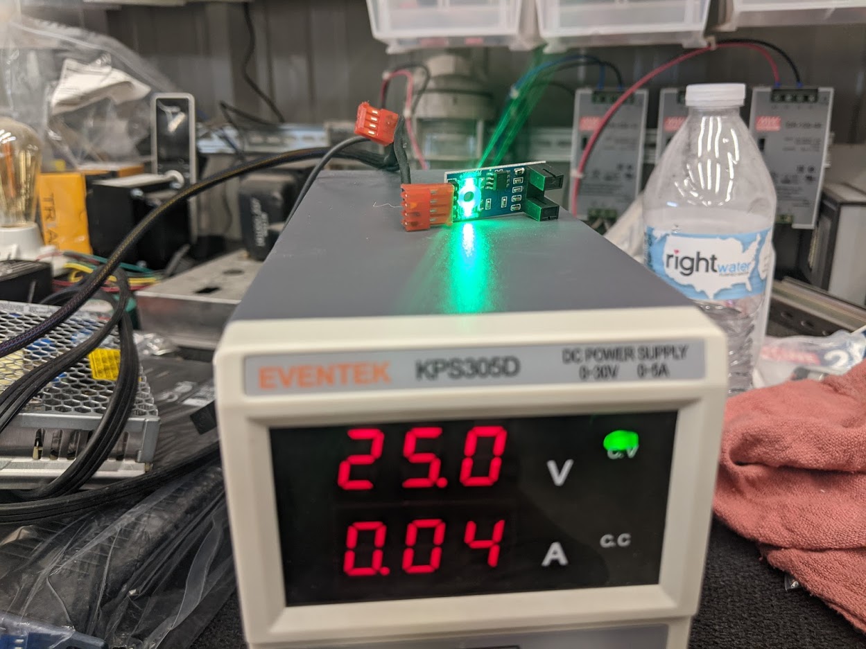
Attachments:
Please Log in or Create an account to join the conversation.
- txtrone
-
Topic Author
- Offline
- Platinum Member
-
- Posts: 384
- Thank you received: 106
You can PM me on Plasmaspider if you would like to know more.
I replied to you email yesterday...
Please Log in or Create an account to join the conversation.
- andypugh
-
- Offline
- Moderator
-
- Posts: 19863
- Thank you received: 4636
Please Log in or Create an account to join the conversation.
- txtrone
-
Topic Author
- Offline
- Platinum Member
-
- Posts: 384
- Thank you received: 106
Have you tested by putting something opaque in the gap then looking at AO and DO voltages relative to Gnd?
I have not, but I will tomorrow first thing. What will that tell me?
Please Log in or Create an account to join the conversation.