
Search Results (Searched for: )
- vibram
17 Dec 2025 09:20
Replied by vibram on topic Ethercat compatible Encoder board tentative STM32F4 + LAN9252
Hello
Thank you for pushing me
I took back your project and build with the SPI2, flash you r eeprom and it worked well, im in OP mode in free run.
As I'm a beginner, my goal is to have a working base (basically yours...) and edit in order to adapt my needs.
Now I have the SPI working well, I will try to integrate my encoder from thise base
Thank you for pushing me
I took back your project and build with the SPI2, flash you r eeprom and it worked well, im in OP mode in free run.
As I'm a beginner, my goal is to have a working base (basically yours...) and edit in order to adapt my needs.
Now I have the SPI working well, I will try to integrate my encoder from thise base
- DEVILHUNTER
17 Dec 2025 08:23
Replied by DEVILHUNTER on topic MESA 7I76 / 7i76e Model
Apologies for reviving this old topic but found a mistake on the diagram that may generate a lot of frustation to anyone trying to use it.
Pin AI3 is missing, so all other digital input pins from so on are displaced 1 position.
Unfortunatelly even if moderators delete the link in both #98901 and #112565 on the forum, the diagram is still appearing as one of the first searchs on search engines. Not sure if OP has a way to change the picture on his cloudfront account.
Pin AI3 is missing, so all other digital input pins from so on are displaced 1 position.
Unfortunatelly even if moderators delete the link in both #98901 and #112565 on the forum, the diagram is still appearing as one of the first searchs on search engines. Not sure if OP has a way to change the picture on his cloudfront account.
- unknown
17 Dec 2025 07:50
Replied by unknown on topic Advantech PCM 9362 freze when opening latency-test
Yeah wifi can be an issue sometimes.
It might be worth looking into some of the services that maybe running not is not required for a cnc machine, CUPS is one for example.
It might be worth looking into some of the services that maybe running not is not required for a cnc machine, CUPS is one for example.
- Sekai
17 Dec 2025 07:29 - 17 Dec 2025 07:42
Replied by Sekai on topic Advantech PCM 9362 freze when opening latency-test
I disable hyperthreading and now it show max 16us and it never froze.
Edit: btw i think i know why it froze.
I had a wifi card put in but now i remove it.
And the latency is better without it.
Edit: btw i think i know why it froze.
I had a wifi card put in but now i remove it.
And the latency is better without it.
- Sekai
17 Dec 2025 06:17
I'l try riocore/LinuxcncRIO later
Last night i did clean install of Debian 12.12
And downloaded :
RTAI Kernel 5.4.258
RTAI modulesernel 5.4.258
LinuxCNC package for RTAI kernel 5.4.258
Now when installed the kernel the message with i915 did not show up.
After a night of latency-test the numbers are ok.
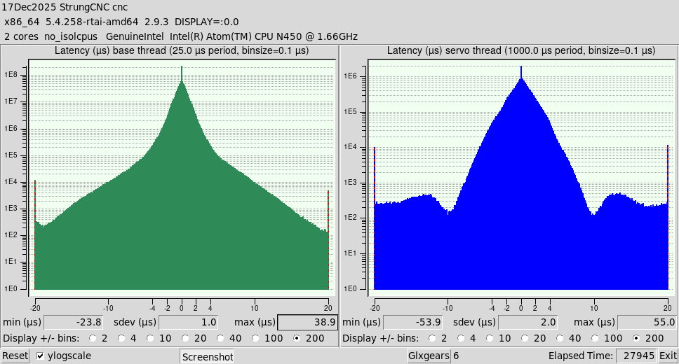
Hyper threading is active that why it say 2 cores.
Replied by Sekai on topic Advantech PCM 9362 freze when opening latency-test
The missing firmware module can safely be ignored.
The above post can be safely ignored as well.
Tho if it is something you can do and can afford, I would recommend looking at the riocore/LinuxcncRIO project as that can connect via ethernet, is creates step/direction in hardware and as such only requires a servo thread. Another plus being you don't require a RTAI kernel. Just mentioning as this might be worth investigating. The developer is very generous with his time as well and the project is very active.
I'l try riocore/LinuxcncRIO later
Last night i did clean install of Debian 12.12
And downloaded :
RTAI Kernel 5.4.258
RTAI modulesernel 5.4.258
LinuxCNC package for RTAI kernel 5.4.258
Now when installed the kernel the message with i915 did not show up.
After a night of latency-test the numbers are ok.
Hyper threading is active that why it say 2 cores.
- zoeper
17 Dec 2025 05:27
Replied by zoeper on topic Avon 3000 Mill retrofit
I missed the "shared home and limit" option.
Thank you for pointing that out!
Thank you for pointing that out!
- frayja2002
17 Dec 2025 03:41 - 17 Dec 2025 08:42
USB pendant button to zero axis was created by frayja2002
Hi all
I have a DragonRise USB board that I am using for a pendant.
Currently I press and hold a button for the speed & then an X Y or Z axis button to jog.
I would like to be able press a zero button & one of the axis to zero that one.
I did see this code for the ini file....
[HALUI]
# add halui MDI commands here (max 64)
MDI_COMMAND = "G10 L20 P0 X0"
MDI_COMMAND = "G10 L20 P0 Y0"
MDI_COMMAND = "G10 L20 P0 Z0"
but I am not sure how to call it from my hal file.
I have attached my ini & the USB part of the hal file.
Any pointers in the right direction would be appreciated.
Thnks
Alex.
After mucking about for a while I would like to be able to do something like this (i think)
#
setp zero-mux4.in0 99 # Setting this input prevents motion unless one of the other buttons is pressed.
setp zero-mux4.in1 02 # Zero X
setp zero-mux4.in2 03 # Zero Y
setp zero-mux4.in3 04 # Zero Z
net zero-btn0 <= zero-mux4.sel0 <= input.0.btn-base
net zero-btn1 <= zero-mux4.sel1 <= input.0.btn-trigger
#net zero-axis => zero-mux4.out => halui.mdi-command-(zero-mux4.out)
Does this sound like how it should be done.
I have a DragonRise USB board that I am using for a pendant.
Currently I press and hold a button for the speed & then an X Y or Z axis button to jog.
I would like to be able press a zero button & one of the axis to zero that one.
I did see this code for the ini file....
[HALUI]
# add halui MDI commands here (max 64)
MDI_COMMAND = "G10 L20 P0 X0"
MDI_COMMAND = "G10 L20 P0 Y0"
MDI_COMMAND = "G10 L20 P0 Z0"
but I am not sure how to call it from my hal file.
I have attached my ini & the USB part of the hal file.
Any pointers in the right direction would be appreciated.
Thnks
Alex.
After mucking about for a while I would like to be able to do something like this (i think)
#
setp zero-mux4.in0 99 # Setting this input prevents motion unless one of the other buttons is pressed.
setp zero-mux4.in1 02 # Zero X
setp zero-mux4.in2 03 # Zero Y
setp zero-mux4.in3 04 # Zero Z
net zero-btn0 <= zero-mux4.sel0 <= input.0.btn-base
net zero-btn1 <= zero-mux4.sel1 <= input.0.btn-trigger
#net zero-axis => zero-mux4.out => halui.mdi-command-(zero-mux4.out)
Does this sound like how it should be done.
- NWE
-
17 Dec 2025 02:02 - 17 Dec 2025 02:18
Replied by NWE on topic Avon 3000 Mill retrofit
Decide which end of the limit you want to home to, then pick shared home+limit for the associated switch(es). You will also need to specify Home search direction and home latch direction in each axis page. I know LinuxCNC has homing to index, but I don't currently have that bit figured out on my current retrofit project.I am trying to get as far as possible using PNCConf as HAL is still foreign to me.
Next would be to get the rest of the E-stop (including overtravel) circuit connected and tested before I hook up the belts.
Homing on this machine used to involve looking for the -vector switches (could be +Vector on Z) and reversing direction off the limit until the index marker is found. Can this be set up using PNCConf as well?
- NWE
-
17 Dec 2025 01:50 - 17 Dec 2025 02:09
forum.linuxcnc.org/9-installing-linuxcnc...tch-behavior?start=0
I see on your schematic, the machine has overtravel switches wired direct to the master e-stop. How did the original controller act when you ran into a vector limit? I wonder if those were being used as "soft limits"? LinuxCNC has that in software , can be set right in your Pncconf, the top 3 or 4 values for each axis config page. I expect the best way to handle it would be to enter your axis measurements in Pncconf such that LinuxCNC's soft limit stops the axis reliably a bit short of activating the vector switches. With shared homing it will be ok to bump the vector switch for homing.
Replied by NWE on topic Avon 3000 Mill retrofit
Good question. I have little to no experience with limit switches in LinuxCNC. Hopefully someone else who knows more about this can enlighten us. As I recall, most machines with oem controllers I've worked on generally e-stop when a limit gets bumped. I did find this:Another observation: If I actuate a limit (+vector or -vector, not the overtravel), the control trips the estop circuit, instead of just holding feed in that direction. is this correct?
forum.linuxcnc.org/9-installing-linuxcnc...tch-behavior?start=0
I see on your schematic, the machine has overtravel switches wired direct to the master e-stop. How did the original controller act when you ran into a vector limit? I wonder if those were being used as "soft limits"? LinuxCNC has that in software , can be set right in your Pncconf, the top 3 or 4 values for each axis config page. I expect the best way to handle it would be to enter your axis measurements in Pncconf such that LinuxCNC's soft limit stops the axis reliably a bit short of activating the vector switches. With shared homing it will be ok to bump the vector switch for homing.
- tommylight
-

16 Dec 2025 23:38
Replied by tommylight on topic Remora 1.1.0 + BTT Octopus – jog overshoot and joint following error
Moved to " Computers and Hardware".
Thank you.
Thank you.
- unknown
16 Dec 2025 21:20
Replied by unknown on topic Advantech PCM 9362 freze when opening latency-test
The missing firmware module can safely be ignored.
The above post can be safely ignored as well.
Tho if it is something you can do and can afford, I would recommend looking at the riocore/LinuxcncRIO project as that can connect via ethernet, is creates step/direction in hardware and as such only requires a servo thread. Another plus being you don't require a RTAI kernel. Just mentioning as this might be worth investigating. The developer is very generous with his time as well and the project is very active.
The above post can be safely ignored as well.
Tho if it is something you can do and can afford, I would recommend looking at the riocore/LinuxcncRIO project as that can connect via ethernet, is creates step/direction in hardware and as such only requires a servo thread. Another plus being you don't require a RTAI kernel. Just mentioning as this might be worth investigating. The developer is very generous with his time as well and the project is very active.
- Sekai
16 Dec 2025 21:01
Replied by Sekai on topic Advantech PCM 9362 freze when opening latency-test
i did notice something weird when i install the kernel.
Its says missing firmware module i915
But the display works great.
Its says missing firmware module i915
But the display works great.
- Hakan
16 Dec 2025 20:29 - 16 Dec 2025 20:29
Replied by Hakan on topic Ethercat compatible Encoder board tentative STM32F4 + LAN9252
It's better I give you a hand in those situations. So you have a version you always can come back to that works.
And then you can be creative on top of that get lost from there.
But what you have described you want to do, you are more or less finished already.
There is of course the whole packaging story, Din-rail? box, other? external power supply, connectors, photo-diodes on encoder input?
Stacking of several units? Can you perhaps use the 16-bit counters and have several counters on board? Is there a MCU with several 32-bit encoders you can use/switch to. Just because it works doesn't mean it is finished. For sure it can be optimized.
Right now it runs in free-run mode, should probably go over to DC-sync mode and there is a bit of programming for that. Same HW though.
Microchip has come out with several schematics for their evaluation boards, here is one ww1.microchip.com/downloads/en/DeviceDoc...PIO16.Mode.Rev.A.pdf Here is another ww1.microchip.com/downloads/aemDocuments...DIG-IO-EVB-REV-B.pdf and you find schematics in my KiCaD files.
And then you can be creative on top of that
But what you have described you want to do, you are more or less finished already.
There is of course the whole packaging story, Din-rail? box, other? external power supply, connectors, photo-diodes on encoder input?
Stacking of several units? Can you perhaps use the 16-bit counters and have several counters on board? Is there a MCU with several 32-bit encoders you can use/switch to. Just because it works doesn't mean it is finished. For sure it can be optimized.
Right now it runs in free-run mode, should probably go over to DC-sync mode and there is a bit of programming for that. Same HW though.
Microchip has come out with several schematics for their evaluation boards, here is one ww1.microchip.com/downloads/en/DeviceDoc...PIO16.Mode.Rev.A.pdf Here is another ww1.microchip.com/downloads/aemDocuments...DIG-IO-EVB-REV-B.pdf and you find schematics in my KiCaD files.
- zoeper
16 Dec 2025 19:34
Replied by zoeper on topic Avon 3000 Mill retrofit
I made some progress today. Hooked up all limit switches and the "E-stop out" output.It functions, but I have trouble measuring the output using a multimeter and I suspect it need to be pulled up (using the 7i77D with sinking outputs.
I did manage to run the Default LinuxCNC logo engraving Gcode without the belts connected, and it was good to see the motors doing their thing at LinuxCNC;s command.
Another observation: If I actuate a limit (+vector or -vector, not the overtravel), the control trips the estop circuit, instead of just holding feed in that direction. is this correct?
I am trying to get as far as possible using PNCConf as HAL is still foreign to me.
Next would be to get the rest of the E-stop (including overtravel) circuit connected and tested before I hook up the belts.
Homing on this machine used to involve looking for the -vector switches (could be +Vector on Z) and reversing direction off the limit until the index marker is found. Can this be set up using PNCConf as well?
I did manage to run the Default LinuxCNC logo engraving Gcode without the belts connected, and it was good to see the motors doing their thing at LinuxCNC;s command.
Another observation: If I actuate a limit (+vector or -vector, not the overtravel), the control trips the estop circuit, instead of just holding feed in that direction. is this correct?
I am trying to get as far as possible using PNCConf as HAL is still foreign to me.
Next would be to get the rest of the E-stop (including overtravel) circuit connected and tested before I hook up the belts.
Homing on this machine used to involve looking for the -vector switches (could be +Vector on Z) and reversing direction off the limit until the index marker is found. Can this be set up using PNCConf as well?
- Chad
16 Dec 2025 19:15
Remora 1.1.0 + BTT Octopus – jog overshoot and joint following error was created by Chad
Hi,I have been fighting with Remora on a Raspberry Pi for about 3 months now and I am running out of ideas, so I’m asking for some help.Hardware / versions
/
parameters, so I cannot slow down the SPI clock from the LinuxCNC side.Because of that I moved to a BTT Octopus with Remora 1.1.0, which gives me
and
so I can reduce SPI speed.What happens on the Octopus
(Values can be changed, this is just what I’m testing now.)
section in my INI
Relevant HAL fragment (Octopus / Remora connection)
(If anything in this mapping looks obviously wrong, please point it out.)What I have already tried
my octopus config.txt:
my .ini file:
my .hal file:
- Raspberry Pi: (model + RAM ).
- BTT Octopus: (exact version, e.g. v1.1, STM32F446).
- LinuxCNC: version from the official RPi image.
- Remora: 1.1.0 – STM32 firmware for the Octopus from the 1.1.0 release, LinuxCNC component compiled from
.Code:remora-1.1.0/LinuxCNC/Components/Remora/remora.c
Code:
SPI_clk_div
Code:
PRU_base_freq
Code:
SPI_clk_div
Code:
PRU_base_freq
- SPI now looks stable: when I run the heater/wire only (no axis motion) I don’t get any “bad SPI payload” at all.
- I load the component like this:
Code:
loadrt remora SPI_clk_div=128 PRU_base_freq=40000
- The motors move, in the correct direction, but I have two problems:
- Jog incremental overshoot
In incremental jog (for example 1 mm or 10 mm) when I press the jog “+” button and release it, the axis moves noticeably more than the requested increment.
It looks like Remora/stepgen continues to output steps for a short time after LinuxCNC has stopped the move. - Joint following error after a few cm of travel
With conservative parameters (see JOINT_0 below) the axis can travel a few centimetres and then I get a joint following error.
With SKR + Remora 0.1.0, using the same HAL/INI values for SCALE, acceleration, max velocity and FERROR, I never had following errors – only the “bad SPI payload” issue.
Code:
[JOINT_0]
Code:
[JOINT_0] TYPE = LINEAR HOME = 0 HOME_OFFSET = -10 MIN_LIMIT = -0.001 MAX_LIMIT = 450 MAX_VELOCITY = 10 MAX_ACCELERATION = 200 STEPGEN_MAXACCEL = 300 SCALE = (current value – was 50 originally) FERROR = 50 MIN_FERROR = 20 HOME_SEARCH_VEL = -1.5 HOME_LATCH_VEL = -0.5 HOME_IGNORE_LIMITS = YES HOME_SEQUENCE = 0
Code:
loadrt remora SPI_clk_div=128 PRU_base_freq=40000 # add remora and motion functions to threads addf remora.read servo-thread addf motion-command-handler servo-thread addf motion-controller servo-thread addf remora.update-freq servo-thread addf remora.write servo-thread # --- Joint 0 (X) --- setp remora.joint.0.scale [JOINT_0]SCALE setp remora.joint.0.maxaccel [JOINT_0]STEPGEN_MAXACCEL net xpos-cmd <= joint.0.motor-pos-cmd => remora.joint.0.pos-cmd net xpos-fb <= remora.joint.0.pos-fb => joint.0.motor-pos-fb net j0enable <= joint.0.amp-enable-out => remora.joint.0.enable
- Reduced
,Code:MAX_VELOCITYandCode:MAX_ACCELERATIONa lot and increasedCode:STEPGEN_MAXACCEL/Code:FERROR. This delays the following error but does not remove it.Code:MIN_FERROR
- Tried to tune
using G‑code (G91 / G0 X100 and measuring real travel). Even with reasonable SCALE values I still see overshoot in incremental jog: the axis moves clearly more than the selected increment.Code:SCALE
- On SKR 1.4 with old Remora 0.1.0, with the same mechanical setup and same SCALE / accel / maxvel / FERROR, jogging and running G‑code worked fine (no following errors, no overshoot). The only issue there is the fixed, too‑fast SPI that causes “bad SPI payload”.
- Is this kind of jog overshoot in incremental mode a known configuration issue with Remora 1.1.0 + Octopus (for example related to PRU_base_freq, servo thread period, or some Remora parameter), or is it more likely that I have a clear mistake in my HAL/INI?
- What SPI / PRU settings do people successfully use on a BTT Octopus with Remora 1.x? Is
andCode:SPI_clk_div=128reasonable, or should I change these?Code:PRU_base_freq=40000
- Does anyone have a working LinuxCNC config (INI/HAL) for Remora 1.1.0 + Octopus in plain step/dir mode and would be willing to share the relevant
line and joint settings?Code:loadrt remora
- Are there any STM32/Octopus‑specific considerations in Remora (different expectations for SCALE, FERROR, etc.) when migrating from an LPC/SKR setup?
- to get rid of the jog overshoot in incremental mode,
- to choose sane parameters so joint following error does not appear every few centimetres at reasonable speeds.
my octopus config.txt:
Code:
{
"Board": "BIGTREETECH OCTOPUS",
"Modules": [
{ "Thread": "Servo", "Type": "Reset Pin", "Comment": "Reset pin", "Pin": "PC_15" },
{ "Thread": "Base", "Type": "SPI", "Comment": "SPI interface to Raspberry Pi", "CS Pin": "PA_4" },
{ "Thread": "Base", "Type": "Stepgen", "Comment": "X - Joint 0 stepgen", "Joint Number": 0, "Step Pin": "PF_13", "Direction Pin": "PF_12", "Enable Pin": "PF_14" },
{ "Thread": "Base", "Type": "Stepgen", "Comment": "Y - Joint 1 stepgen", "Joint Number": 1, "Step Pin": "PG_0", "Direction Pin": "PG_1", "Enable Pin": "PF_15" },
{ "Thread": "Base", "Type": "Stepgen", "Comment": "U - Joint 2 stepgen", "Joint Number": 2, "Step Pin": "PF_11", "Direction Pin": "PG_3", "Enable Pin": "PG_5" },
{ "Thread": "Base", "Type": "Stepgen", "Comment": "V - Joint 3 stepgen", "Joint Number": 3, "Step Pin": "PG_4", "Direction Pin": "PC_1", "Enable Pin": "PA_0" },
{ "Thread": "Base", "Type": "Stepgen", "Comment": "B - Joint 4 stepgen", "Joint Number": 4, "Step Pin": "PF_9", "Direction Pin": "PF_10", "Enable Pin": "PG_2" },
{
"Thread": "Servo",
"Type": "Digital Pin",
"Comment": "X limit",
"Pin": "PG_6",
"Mode": "Input",
"Data Bit": 0
},
{
"Thread": "Servo",
"Type": "Digital Pin",
"Comment": "Y limit",
"Pin": "PG_9",
"Mode": "Input",
"Data Bit": 1
},
{
"Thread": "Servo",
"Type": "Digital Pin",
"Comment": "U limit",
"Pin": "PG_10",
"Mode": "Input",
"Data Bit": 2
},
{
"Thread": "Servo",
"Type": "Digital Pin",
"Comment": "V limit",
"Pin": "PG_11",
"Mode": "Input",
"Data Bit": 3
},
{
"Thread": "Servo",
"Type": "Digital Pin",
"Comment": "B limit",
"Pin": "PG_12",
"Mode": "Input",
"Data Bit": 4
},
{
"Thread": "Servo",
"Type": "PWM",
"Comment": "PWM for heating",
"SP[i]": 5,
"PWM Pin": "PA_1",
"PWM Max": 256,
"Hardware PWM": "True",
"Variable Freq": "True",
"Period SP[i]": 1,
"Period us": 500
}
]
}
my .ini file:
Code:
[EMC]
MACHINE = Remora-XYUV
DEBUG = 0
VERSION = 1.1
[DISPLAY]
DISPLAY = axis
EDITOR = gedit
FOAM = 1
GEOMETRY = XY;UV
POSITION_OFFSET = RELATIVE
POSITION_FEEDBACK = ACTUAL
ARCDIVISION = 64
GRIDS = 10mm 20mm 50mm 100mm
MAX_FEED_OVERRIDE = 1.2
MIN_SPINDLE_OVERRIDE = 0.5
MAX_SPINDLE_OVERRIDE = 1.2
DEFAULT_LINEAR_VELOCITY = 2.50
MIN_LINEAR_VELOCITY = 0
MAX_LINEAR_VELOCITY = 25.00
DEFAULT_ANGULAR_VELOCITY = 36.00
MIN_ANGULAR_VELOCITY = 0
MAX_ANGULAR_VELOCITY = 45.00
INTRO_GRAPHIC = linuxcnc.gif
INTRO_TIME = 5
PROGRAM_PREFIX = ~/linuxcnc/nc_files
OPEN_FILE = ./foam.ngc
INCREMENTS = 5mm 1mm .5mm .1mm .05mm .01mm .005mm
[KINS]
JOINTS = 5
KINEMATICS = trivkins coordinates=XYUVB
[FILTER]
PROGRAM_EXTENSION = .py Python Script
py = python
[TASK]
TASK = milltask
CYCLE_TIME = 0.010
[RS274NGC]
PARAMETER_FILE = linuxcnc.var
[EMCMOT]
EMCMOT = motmod
COMM_TIMEOUT = 1.0
COMM_WAIT = 0.010
BASE_PERIOD = 100000
SERVO_PERIOD = 1000000
[HAL]
HALFILE = remora-xyuvb.hal
POSTGUI_HALFILE = postgui_call_list.hal
[TRAJ]
AXES = 5
COORDINATES = X Y U V B
LINEAR_UNITS = mm
ANGULAR_UNITS = degree
DEFAULT_LINEAR_VELOCITY = 2.50
MAX_LINEAR_VELOCITY = 25.00
NO_FORCE_HOMING = 1
[EMCIO]
EMCIO = io
CYCLE_TIME = 0.100
TOOL_TABLE = tool.tbl
EXTERNAL_OUTPUT_0 = motion.analog-out-00
[AXIS_X]
MAX_VELOCITY = 23.75
MAX_ACCELERATION = 750.0
MIN_LIMIT = 10
MAX_LIMIT = 450
[JOINT_0]
TYPE = LINEAR
HOME = 0
HOME_OFFSET = -10
MIN_LIMIT = -0.001
MAX_LIMIT = 450
MAX_VELOCITY = 23.75
MAX_ACCELERATION = 750.0
STEPGEN_MAXACCEL = 937.5
SCALE = 50
FERROR = 1
MIN_FERROR = .25
HOME_OFFSET = 0.000
HOME_SEARCH_VEL = -1.5
HOME_LATCH_VEL = -0.5
HOME_IGNORE_LIMITS = YES
HOME_SEQUENCE = 0
[AXIS_Y]
MAX_VELOCITY = 23.75
MAX_ACCELERATION = 750.0
MIN_LIMIT = -0.001
MAX_LIMIT = 200.0
[JOINT_1]
TYPE = LINEAR
HOME = 0
HOME_OFFSET = -10
MIN_LIMIT = -0.001
MAX_LIMIT = 200.0
MAX_VELOCITY = 23.75
MAX_ACCELERATION = 750.0
STEPGEN_MAXACCEL = 937.5
SCALE = -50
FERROR = 1
MIN_FERROR = .25
HOME_OFFSET = 0.000
HOME_SEARCH_VEL = -1.5
HOME_LATCH_VEL = -0.5
HOME_IGNORE_LIMITS = YES
HOME_SEQUENCE = 1
[AXIS_U]
MAX_VELOCITY = 23.75
MAX_ACCELERATION = 750.0
MIN_LIMIT = 10
MAX_LIMIT = 450
[JOINT_2]
TYPE = LINEAR
HOME = 0
HOME_OFFSET = -10
MIN_LIMIT = -0.001
MAX_LIMIT = 450
MAX_VELOCITY = 23.75
MAX_ACCELERATION = 750.0
STEPGEN_MAXACCEL = 937.5
SCALE = -50
FERROR = 1
MIN_FERROR = .25
HOME_OFFSET = 0.000
HOME_SEARCH_VEL = -1.5
HOME_LATCH_VEL = -0.5
HOME_IGNORE_LIMITS = YES
HOME_SEQUENCE = 0
[AXIS_V]
MAX_VELOCITY = 23.75
MAX_ACCELERATION = 750.0
MIN_LIMIT = -0.001
MAX_LIMIT = 200.0
[JOINT_3]
TYPE = LINEAR
HOME = 0
HOME_OFFSET = -10
MIN_LIMIT = -0.001
MAX_LIMIT = 200.0
MAX_VELOCITY = 23.75
MAX_ACCELERATION = 750.0
STEPGEN_MAXACCEL = 937.5
SCALE = -50
FERROR = 1
MIN_FERROR = .25
HOME_OFFSET = 0.000
HOME_SEARCH_VEL = -1.5
HOME_LATCH_VEL = -0.5
HOME_IGNORE_LIMITS = YES
HOME_SEQUENCE = 1
[AXIS_B]
MAX_VELOCITY = 23.75
MAX_ACCELERATION = 750.0
MIN_LIMIT = -0.001
MAX_LIMIT = 200.0
[JOINT_4]
TYPE = LINEAR
HOME = 0
HOME_OFFSET = 1
MIN_LIMIT = -0.001
MAX_LIMIT = 200.0
MAX_VELOCITY = 23.75
# MAX_ACCELERATION = 750.0
MAX_ACCELERATION = 500.0
# STEPGEN_MAXACCEL = 937.5
STEPGEN_MAXACCEL = 537.5
SCALE = 50
FERROR = 1
MIN_FERROR = .25
HOME_OFFSET = 0.000
HOME_SEARCH_VEL = 1
HOME_LATCH_VEL = 0.1
HOME_IGNORE_LIMITS = YES
HOME_SEQUENCE = 2
my .hal file:
Code:
# --- load the realtime components
loadrt [KINS]KINEMATICS
loadrt [EMCMOT]EMCMOT base_period_nsec=[EMCMOT]BASE_PERIOD servo_period_nsec=[EMCMOT]SERVO_PERIOD num_joints=5
loadrt remora
# --- estop loopback, SPI comms enable and feedback
net user-enable-out <= iocontrol.0.user-enable-out => remora.SPI-enable
net user-request-enable <= iocontrol.0.user-request-enable => remora.SPI-reset
net remora-status <= remora.SPI-status => iocontrol.0.emc-enable-in
# --- add the remora and motion functions to threads
addf remora.read servo-thread
addf motion-command-handler servo-thread
addf motion-controller servo-thread
addf remora.update-freq servo-thread
addf remora.write servo-thread
# ------- Joint 0 (X / Tower 1) -------
setp remora.joint.0.scale [JOINT_0]SCALE
setp remora.joint.0.maxaccel [JOINT_0]STEPGEN_MAXACCEL
net xpos-cmd <= joint.0.motor-pos-cmd => remora.joint.0.pos-cmd
net j0pos-fb <= remora.joint.0.pos-fb => joint.0.motor-pos-fb
net j0enable <= joint.0.amp-enable-out => remora.joint.0.enable
net X-stop remora.input.0 => joint.0.home-sw-in joint.0.neg-lim-sw-in joint.0.pos-lim-sw-in
# ------- Joint 1 (Y / Tower 1) -------
setp remora.joint.1.scale [JOINT_1]SCALE
setp remora.joint.1.maxaccel [JOINT_1]STEPGEN_MAXACCEL
net ypos-cmd <= joint.1.motor-pos-cmd => remora.joint.1.pos-cmd
net j1pos-fb <= remora.joint.1.pos-fb => joint.1.motor-pos-fb
net j1enable <= joint.1.amp-enable-out => remora.joint.1.enable
net Y-min remora.input.1 => joint.1.home-sw-in joint.1.neg-lim-sw-in joint.1.pos-lim-sw-in
# ------- Joint 2 (U / Tower 2) -------
setp remora.joint.2.scale [JOINT_2]SCALE
setp remora.joint.2.maxaccel [JOINT_2]STEPGEN_MAXACCEL
net upos-cmd <= joint.2.motor-pos-cmd => remora.joint.2.pos-cmd
net j2pos-fb <= remora.joint.2.pos-fb => joint.2.motor-pos-fb
net j2enable <= joint.2.amp-enable-out => remora.joint.2.enable
net U-min remora.input.2 => joint.2.home-sw-in joint.2.neg-lim-sw-in joint.2.pos-lim-sw-in
# ------- Joint 3 (V / Tower 2) -------
setp remora.joint.3.scale [JOINT_3]SCALE
setp remora.joint.3.maxaccel [JOINT_3]STEPGEN_MAXACCEL
net vpos-cmd <= joint.3.motor-pos-cmd => remora.joint.3.pos-cmd
net j3pos-fb <= remora.joint.3.pos-fb => joint.3.motor-pos-fb
net j3enable <= joint.3.amp-enable-out => remora.joint.3.enable
net V-min remora.input.3 => joint.3.home-sw-in joint.3.neg-lim-sw-in joint.3.pos-lim-sw-in
# ------- Joint 4 (B / Rotary Table) -------
setp remora.joint.4.scale [JOINT_4]SCALE
setp remora.joint.4.maxaccel [JOINT_4]STEPGEN_MAXACCEL
net bpos-cmd <= joint.4.motor-pos-cmd => remora.joint.4.pos-cmd
net j4pos-fb <= remora.joint.4.pos-fb => joint.4.motor-pos-fb
net j4enable <= joint.4.amp-enable-out => remora.joint.4.enable
net B-min remora.input.4 => joint.4.home-sw-in joint.4.neg-lim-sw-in joint.4.pos-lim-sw-in
net heat_pwm motion.analog-out-00 => remora.SP.5
Time to create page: 0.384 seconds