TCP 5-axis kinematics
- jsskangas
- Offline
- Premium Member
-

Less
More
- Posts: 144
- Thank you received: 9
04 Feb 2018 18:54 #105412
by jsskangas
Replied by jsskangas on topic TCP 5-axis kinematics
Hello
Small progress has been done, it is not a complete solution, or usable one at the moment.
Procedure is following at the moment:
run code in linear kinematics.
press $ to joint mode
switch TCP kinematics on
press $ to world mode
Apparently switching from joint to world mode, will update axis positions upwards.
This way tool picks up its current position in rotated coordinate system.
There could be a command that updates axis position upwards so that joint world mode cycle would not be needed.
But at the moment it seems to work if whole process could be preformed during Gcode run.
There are some draw backs as well.
If I remember correctly joint mode can not be activated during Gcode run.
Below is just my idea and I have not tested it yet.
I think this could be over come by running custom Mcode that will chance to joint mode and then activate TCP(change kinematic model) and switch to world mode.
Initial idea is Rubys, I'm just testing it.
Please Log in or Create an account to join the conversation.
- Grotius
-

- Offline
- Platinum Member
-

Less
More
- Posts: 2419
- Thank you received: 2349
04 Feb 2018 20:51 #105417
by Grotius
Replied by Grotius on topic TCP 5-axis kinematics
@Kangas,
Have you got some picture's of what you are doing?
I remembered you want to write to hal value's earler in this topic? Did you find this code?
You can do this with float or bit values if you want. examples can be done if it's still on your list.
5 axis tcp (tool center point) is for linux possible. But for most of cnc program's not done.
With the upgrade to joint mode, things are changed in hard way. I think they will be corrected in short time, so limitations
will be limited to e-stop.
Maybe post some nice pic's of your work !!
Please Log in or Create an account to join the conversation.
- jsskangas
- Offline
- Premium Member
-
Less
More
- Posts: 144
- Thank you received: 9
04 Feb 2018 21:46 - 04 Feb 2018 21:58 #105421
by jsskangas
Replied by jsskangas on topic TCP 5-axis kinematics
Hello
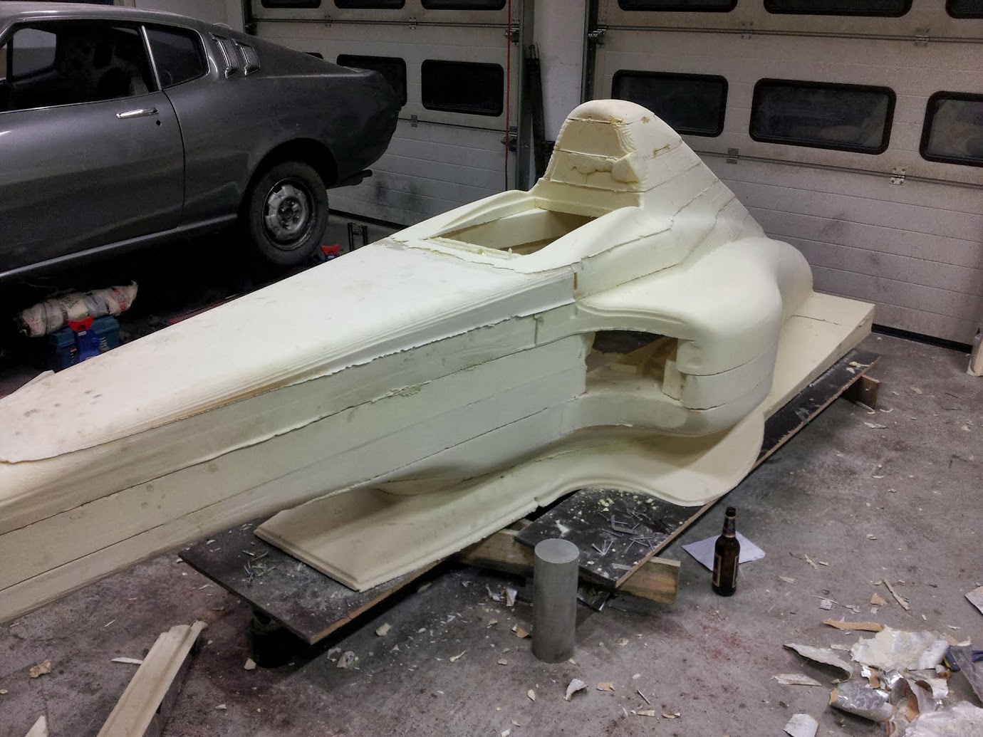
Mainly Im machining some part to my projects like this one:
goo.gl/photos/f7dNbH5akwFsL6MY6
Those parts are mostly prismatic so no full 5-axis needed in there.
Full 5 axis tool path's I use for machining impellers and turbine wheels.
At the moment i use loan machine for those...
I did look at the code and am still not certain what is wrong with it.
It changes kinematics so Code works and input HAL pins.
Values are written in pins in those functions that actually calculates forward and inverse kinematics.
If I make changes to kinematics I can verify that those. so Im compiling a correct file.
But out pin values wont change. I just need this for debugging code, so does only slow down the process.
There is still one this that I have not tested, output pins are not connected anywhere, that could affect...
Last edit: 04 Feb 2018 21:58 by jsskangas.
Please Log in or Create an account to join the conversation.
- Grotius
-
- Offline
- Platinum Member
-
Less
More
- Posts: 2419
- Thank you received: 2349
04 Feb 2018 22:13 - 04 Feb 2018 22:16 #105424
by Grotius
Replied by Grotius on topic TCP 5-axis kinematics
Hi,
If you show a example of 5 axis g-code, can be 10 or 100 lines, i can try to simulate it for you and give my opinion
about possibilities.
Nice toolpath's by the way. Is it a V12 engine inside?
I like too see a picture of what you are doing with linuxcnc.
If you show a example of 5 axis g-code, can be 10 or 100 lines, i can try to simulate it for you and give my opinion
about possibilities.
Nice toolpath's by the way. Is it a V12 engine inside?
I like too see a picture of what you are doing with linuxcnc.
Last edit: 04 Feb 2018 22:16 by Grotius.
Please Log in or Create an account to join the conversation.
- jsskangas
- Offline
- Premium Member
-
Less
More
- Posts: 144
- Thank you received: 9
05 Feb 2018 09:43 - 05 Feb 2018 12:59 #105432
by jsskangas
Replied by jsskangas on topic TCP 5-axis kinematics
Hello
I do not see your point?
I do not have problem with 5-axis tool path's, making those and simulating them is easy part.
Problem is transferring between two different kinematic models inside linuxcnc.
TCP (rotating coordinate system) and straight forward linear.
"I like too see a picture of what you are doing with linuxcnc."
You are looking at them. ( goo.gl/photos/f7dNbH5akwFsL6MY6 )
all those parts except that impeller is made with Linuxcnc.
That old mori is running linuxcnc and 4kW indramat servos + nikken 5ax120, 5 axis table.
Last edit: 05 Feb 2018 12:59 by jsskangas.
Please Log in or Create an account to join the conversation.
- jsskangas
- Offline
- Premium Member
-
Less
More
- Posts: 144
- Thank you received: 9
17 Feb 2018 12:11 - 17 Feb 2018 13:14 #106072
by jsskangas
Replied by jsskangas on topic TCP 5-axis kinematics
3D-Master , everyone else can use this as well.
Use is on your own risk!!!!!!
Read this first:
This is Swiveling subProgram for BC table table machine.
I have not yet tested it my self, but math should work.
I tested it and made small change, i inverted BC axis values in indexing command.
G00 G90 B[-#<theta>] C[-#<iota>]
Rename file to rotate.ngc
It is mandatory that you machine has axes that has been properly defined.
we always command tool to move not machine,
this means that machine axis that moves tool is non-inverted and move along machine axis.
Machine axis that moves part are always inverted.
Additionally your machine you must have axis homing from servo index pulse, other vice this is not accurate enough.
In subprogram there are some parameters that you have to define.
First one is rotary point, this is center of your C axis in XY machine coordinate (G53) and height of B axis in Z.
Second is Vx that is axis difference in X direction between C axis and B axis rotation points. (In Nikken 5AX120 this is close to zero)
There is also Vz but that is not needed.
Subprogram reads automatically what zero point you are using and calculates offset in rotated coordinates.
But it does this only for zeropoint that is active !!
All other zeropoints will be shifted, but will be incorrect !!
This subprogram uses G52 to offset coordinate system, and G52 affects to all other zeropoints as well.
Last edit: 17 Feb 2018 13:14 by jsskangas.
Please Log in or Create an account to join the conversation.
- 3D-Master
- Offline
- Elite Member
-

Less
More
- Posts: 235
- Thank you received: 5
28 Feb 2018 22:39 #106771
by 3D-Master
Replied by 3D-Master on topic TCP 5-axis kinematics
Sorry for the late reply,
no i have not yet tested it, also unfortunately i dont have time for it atm.
anyways thanks for your help!
no i have not yet tested it, also unfortunately i dont have time for it atm.
anyways thanks for your help!
Please Log in or Create an account to join the conversation.
- 3D-Master
- Offline
- Elite Member
-
Less
More
- Posts: 235
- Thank you received: 5
02 Mar 2018 22:08 #106865
by 3D-Master
Replied by 3D-Master on topic TCP 5-axis kinematics
So is this calculation absolute or incremental? I mean can i say for example M140 P30 Q20 (equivalent for G0 B30 C20) and after that M140 P40 Q25 or do i have to say M140 P0 Q0 (or even M140 P-30 Q-20 ?) in order to be able to swivel correctly to the next angle?
Edit: better explained = Does M140 P30 and after that again M140 P30 add to 60 or does it stay at 30?
Also you mean this affects all other Zero points (this could be a problem because i use G59.3 as my Tool Touch probe offset)
Edit: better explained = Does M140 P30 and after that again M140 P30 add to 60 or does it stay at 30?
Also you mean this affects all other Zero points (this could be a problem because i use G59.3 as my Tool Touch probe offset)
Please Log in or Create an account to join the conversation.
- jsskangas
- Offline
- Premium Member
-
Less
More
- Posts: 144
- Thank you received: 9
03 Mar 2018 07:07 - 03 Mar 2018 07:25 #106872
by jsskangas
Replied by jsskangas on topic TCP 5-axis kinematics
Hello
At the moment it is intended to be absolute.
There is other option alternative to G52.
You will dedicate one zero point for this use.
Instead of using G52 you will use G10 L2 Pn ......
but in this you need to give absolute XYZ coordinates of rotated zeropoint relative to machine zeropoint.
This can be calculated: orginal + rotated relative to orginal.
Then activate your zeropoint.
Last edit: 03 Mar 2018 07:25 by jsskangas.
Please Log in or Create an account to join the conversation.
- jsskangas
- Offline
- Premium Member
-
Less
More
- Posts: 144
- Thank you received: 9
01 Apr 2018 13:00 #108210
by jsskangas
Replied by jsskangas on topic TCP 5-axis kinematics
Hello
I'm almost got this done.
I made kinematics that don't need machine zero or zero point to be located at rotary center.
It can change between kinematics when rotary axes are at zero.
I made exel file to try kinematics, before trying them in machine.
I solved kinematic change problem by writing a new post processor and NC code simulation environment (CSE simulation) for SIEMENS NX CAM.
It changes to TCP mode when rotary's are zero , post can drive tool safely to start of toolpath safely, regardless of which coordinate mode it is running.
I made changes to CSE simulation model, I added indexing subprogram to simulation model.
This way simulation model will act exact same as real machine when subprogram is used to offset zeropoint when rotary's are indexed.
Today and tomorrow, I will try out these kinematics in my machine.
Indexing subprogram is already tested and working.
I will update and attach latest subprogram and kinematics files, after testing them.
i will also link some YouTube video after successful run.
Please Log in or Create an account to join the conversation.
Time to create page: 1.907 seconds