- Configuring LinuxCNC
- Advanced Configuration
- New compensation component for engraving and 3D Printing
New compensation component for engraving and 3D Printing
- ThomasB
- Offline
- New Member
-

Less
More
- Posts: 2
- Thank you received: 1
06 Jul 2020 17:07 - 06 Jul 2020 17:08 #173763
by ThomasB
Replied by ThomasB on topic New compensation component for engraving and 3D Printing
Hi,
I have the feeling this thread was somehow hijacked.
Coming back to the original topic, I would like to thank @scotta for this module. It appears to be exactly what i am looking for.
However, I have to admit that the documentation is much too short for me.
After about half a day searching the net I found that the grid-file probe-results.txt can be generated with an example file
grid-probe.ngc that actually comes with LinuxCNC. That's a frustrating newby experience.
After another half day of research I decided that the remark:
"... external offsets must be enabled ..."
could mean to copy all files from ~/linuxcnc/configs/sim/axis/external_offsets/ to the new config directory.
But now I'm stuck with something where I get almost no search results at all from Big-G and others, the error message now is:
./Compensate.hal:103: Pin 'axis.x.pos-cmd' does not exist
Where Compensate is the name of the configuration and this hal file includes in line 103
net xpos-cmd <= axis.x.pos-cmd => compensation.x-pos
which throws the error.
I have no clue where or how the Pin axis.x.pos-cmd gets defined???
Can anyone help?
Last edit: 06 Jul 2020 17:08 by ThomasB.
Please Log in or Create an account to join the conversation.
- rodw
-

- Away
- Platinum Member
-

Less
More
- Posts: 11633
- Thank you received: 3916
06 Jul 2020 21:06 #173773
by rodw
Replied by rodw on topic New compensation component for engraving and 3D Printing
You need to be running V2.8 and above for the external offsets feature. The pins are documented here
linuxcnc.org/docs/2.8/html/man/man9/motion.9.html
linuxcnc.org/docs/2.8/html/man/man9/motion.9.html
Please Log in or Create an account to join the conversation.
- ThomasB
- Offline
- New Member
-

Less
More
- Posts: 2
- Thank you received: 1
07 Jul 2020 06:04 #173814
by ThomasB
Replied by ThomasB on topic New compensation component for engraving and 3D Printing
Thanks, for pointing that out, it explains a lot!
I found the webpage with the explanation as one of the very few search results, but did not realize the version constraint.
I'm on 2.7.15 still.
But that will probably change within this week .
.
I found the webpage with the explanation as one of the very few search results, but did not realize the version constraint.
I'm on 2.7.15 still.
But that will probably change within this week
Please Log in or Create an account to join the conversation.
- SrLange61
-

- Offline
- Junior Member
-

Less
More
- Posts: 38
- Thank you received: 5
27 Jan 2022 06:22 - 27 Jan 2022 06:29 #233255
by SrLange61
Replied by SrLange61 on topic New compensation component for engraving and 3D Printing
Hi
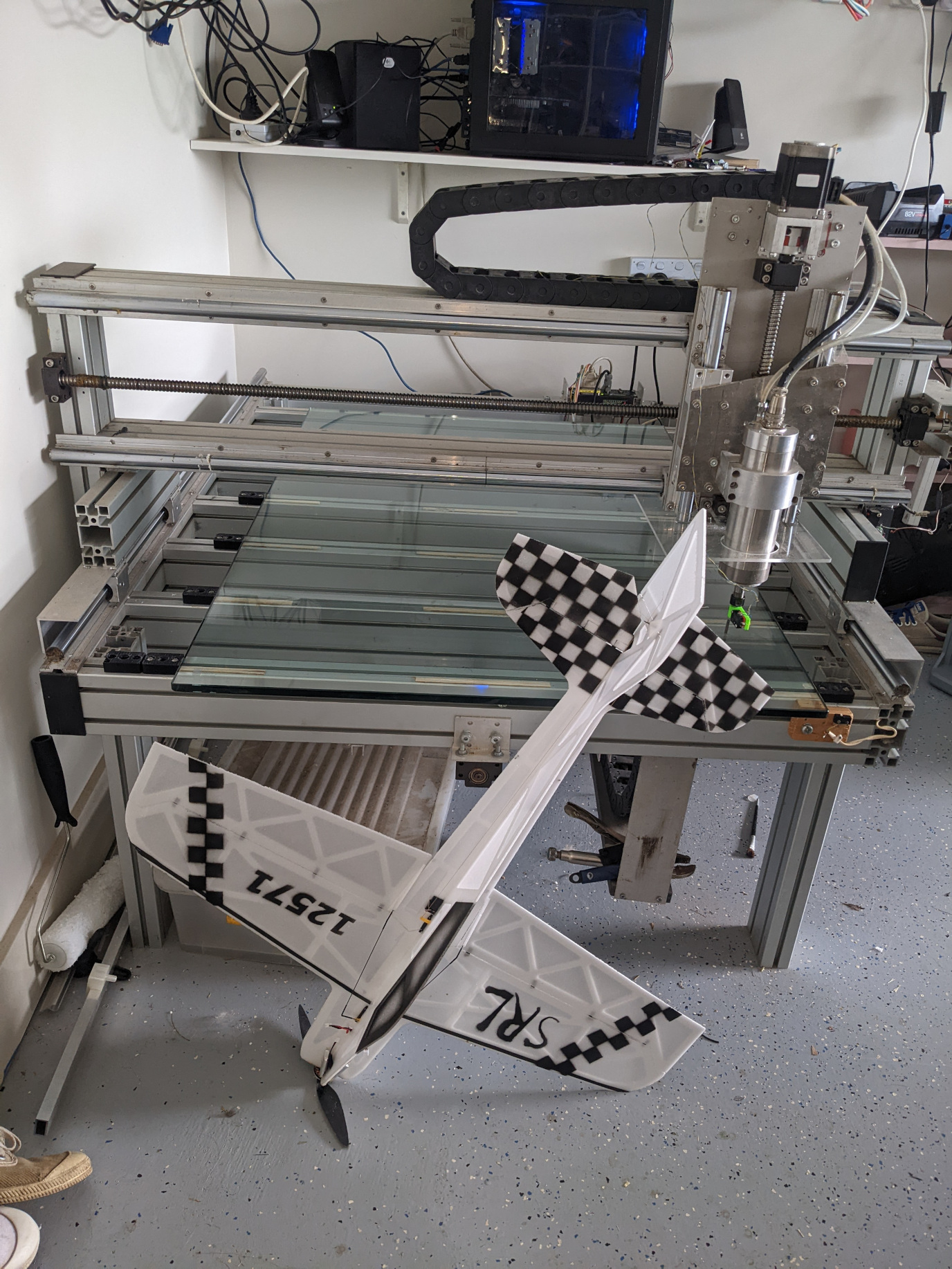
I'm keen to get this going on my CNC to cut and mill Depron. Glass is .3mm up in a area. Its a standard 64bit linuxCNC DEB install. First it needed Scipy so I did a "sudo apt-get install python-scipy" ?
Now this -
Debug file information:Note: Using POSIX realtime./custom.hal:4: python exited without becoming ready1306Stopping realtime threadsUnloading hal componentsNote: Using POSIX realtime
Any ideas?
srl
Last edit: 27 Jan 2022 06:29 by SrLange61.
Please Log in or Create an account to join the conversation.
- SrLange61
-

- Offline
- Junior Member
-

Less
More
- Posts: 38
- Thank you received: 5
30 Jan 2022 04:52 #233514
by SrLange61
Replied by SrLange61 on topic New compensation component for engraving and 3D Printing
My compensation.py file was formated wrong, I did a cut and paste instead of a download.
It now loads up fine.
I now need to work out the comands as my hal file uses joint's.
srl
It now loads up fine.
I now need to work out the comands as my hal file uses joint's.
srl
Please Log in or Create an account to join the conversation.
- SrLange61
-

- Offline
- Junior Member
-

Less
More
- Posts: 38
- Thank you received: 5
01 Feb 2022 09:01 #233693
by SrLange61
Replied by SrLange61 on topic New compensation component for engraving and 3D Printing
I'm having a problem with the hal lines. I have a standard Stepconfig set-up.
With two "net xpos-cmd" lines it has a config error.
Commenting out the the first- "#net xpos-cmd joint.0.motor-pos-cmd => stepgen.0.position-cmd"
the program runs but I get a "joint 0 following error" when I move the tool.
Any ideas ?
With two "net xpos-cmd" lines it has a config error.
Commenting out the the first- "#net xpos-cmd joint.0.motor-pos-cmd => stepgen.0.position-cmd"
the program runs but I get a "joint 0 following error" when I move the tool.
Any ideas ?
Please Log in or Create an account to join the conversation.
- alkabal
- Offline
- Platinum Member
-

Less
More
- Posts: 476
- Thank you received: 52
03 Feb 2022 08:19 - 03 Feb 2022 08:19 #233860
by alkabal
Replied by alkabal on topic New compensation component for engraving and 3D Printing
Hello
I will try to use your compensation component, instalaton was fine and load correctly, thanks you for sharing that.
Some time ago you will speak about sharing your subroutines for map generation.
It is something possible possible ? ( i will like to add z grid creation button in my Axis panel screen)
Best regards
Last edit: 03 Feb 2022 08:19 by alkabal.
Please Log in or Create an account to join the conversation.
- alkabal
- Offline
- Platinum Member
-

Less
More
- Posts: 476
- Thank you received: 52
03 Feb 2022 14:46 - 03 Feb 2022 16:28 #233881
by alkabal
Replied by alkabal on topic New compensation component for engraving and 3D Printing
I have found this topic with interesting link for Autoleveler
forum.linuxcnc.org/38-general-linuxcnc-q...to-linuxcnc?start=10
Not tested for now but it seem to create a ngc file correctly, now is time to find a way for create equivalent file with my python code.
I think i will not be "very difficult" to calculate point but i need to find how to create file and make this working correctly is another things lool.
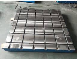
At this point the major problem i can see is how to take care for manage to probe a T solt table ? so any help are welcome for this mathematic problem.
The goal is to embed all the stuff inside "probe screen NG" i hope i can use other value from regular probe config but need to add (6 entry box needed for "XY start" "XY end" "XY row") or (5 entry box
r "XY start" "XY end" "XY spacing")
Br
Edit : i will think for Tslot table to add fixed value in ini file but unfortunatly i think that i'm not able to create the math stuff :
"XY first length" from machine 0 for first groove
"XY groove width"
"XY plate width"
Max size can be checked with ini file
[AXIS_X]
MIN_LIMIT = -0.11
MAX_LIMIT = 356.11
Edit 2 : this was perfect if we also can use tool setter position + dimension for prevent probing in this area
Attachments:
Last edit: 03 Feb 2022 16:28 by alkabal.
Please Log in or Create an account to join the conversation.
- itsme
- Offline
- Senior Member
-

Less
More
- Posts: 78
- Thank you received: 21
03 Feb 2022 16:39 #233887
by itsme
Replied by itsme on topic New compensation component for engraving and 3D Printing
There is a sample ngc file named gridprobe.ngc.
You can use it as a starting point.
You can use it as a starting point.
The following user(s) said Thank You: alkabal
Please Log in or Create an account to join the conversation.
- alkabal
- Offline
- Platinum Member
-

Less
More
- Posts: 476
- Thank you received: 52
09 Feb 2022 20:30 - 09 Feb 2022 20:32 #234422
by alkabal
Replied by alkabal on topic New compensation component for engraving and 3D Printing
Hello
Is i'm the only one having a possible little issue with your compensation component ?
I have noticed if you activate/unactivate the "compensation.enable-in" i can see my machine cumulating the offset.
I think this is because after disable compensation the machine stay in place.
I appologize if this is not understandable.
Edit : it is a good idea to try to return to old position before stoping the component ???
Last edit: 09 Feb 2022 20:32 by alkabal.
Please Log in or Create an account to join the conversation.
- Configuring LinuxCNC
- Advanced Configuration
- New compensation component for engraving and 3D Printing
Time to create page: 0.172 seconds


