
- Posts: 711
- Thank you received: 9
Replacing Advanced Motion Controls "brush type 12A8 with "Axcent" amplifier
- new2linux
- Offline
- Platinum Member
-

Less
More
5 years 11 months ago - 5 years 11 months ago #189703
by new2linux
Replied by new2linux on topic Replacing Advanced Motion Controls "brush type 12A8 with "Axcent" amplifier
Todd, Many thanks! I have tried several ranges of many combinations, attached is 20"/min feed. Not shore what to be looking at or for. This is as quick of feed as I have had so far, more feed and the oscillation starts.
Many thanks!
The settings are: P.115; I.001; D.01; FF1-.001; FF2-.0003; Db.0004
This is a pic of the pid trace crossing over (several times in single 24"/min test) the velocity trace. Settings P.111; I.001; D .05; FF1 .001; FF2 .003; DeadBand .00001
many thanks!
Many thanks!
The settings are: P.115; I.001; D.01; FF1-.001; FF2-.0003; Db.0004
This is a pic of the pid trace crossing over (several times in single 24"/min test) the velocity trace. Settings P.111; I.001; D .05; FF1 .001; FF2 .003; DeadBand .00001
many thanks!
Last edit: 5 years 11 months ago by new2linux.
Please Log in or Create an account to join the conversation.
- Todd Zuercher
- Offline
- Platinum Member
-
Less
More
- Posts: 4793
- Thank you received: 1480
5 years 11 months ago #189750
by Todd Zuercher
Replied by Todd Zuercher on topic Replacing Advanced Motion Controls "brush type 12A8 with "Axcent" amplifier
I'm sorry but how you have halscope configured just isn't showing me anything useful. I usually use an incremental jog set for a move long enough that I can see all portions of the move, at rest, acceleration, cruise, deceleration, and at rest again, all on the screen at the same time. I also usually watch the axis velocity command and use it as the trigger source.
The following user(s) said Thank You: new2linux
Please Log in or Create an account to join the conversation.
- new2linux
- Offline
- Platinum Member
-
Less
More
- Posts: 711
- Thank you received: 9
5 years 11 months ago #189779
by new2linux
Replied by new2linux on topic Replacing Advanced Motion Controls "brush type 12A8 with "Axcent" amplifier
Todd, Thanks for your continued support!! I used the velocity as the source as per your suggestion. This is a pic of most recent tuning settings: Feed22"/min; P .111; D .05; FF1 .001; FF2 .0001; DEADBAND .00001
Many thanks

Many thanks
Please Log in or Create an account to join the conversation.
- Todd Zuercher
- Offline
- Platinum Member
-
Less
More
- Posts: 4793
- Thank you received: 1480
5 years 11 months ago - 5 years 11 months ago #189823
by Todd Zuercher
Replied by Todd Zuercher on topic Replacing Advanced Motion Controls "brush type 12A8 with "Axcent" amplifier
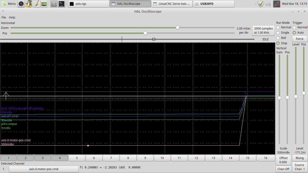
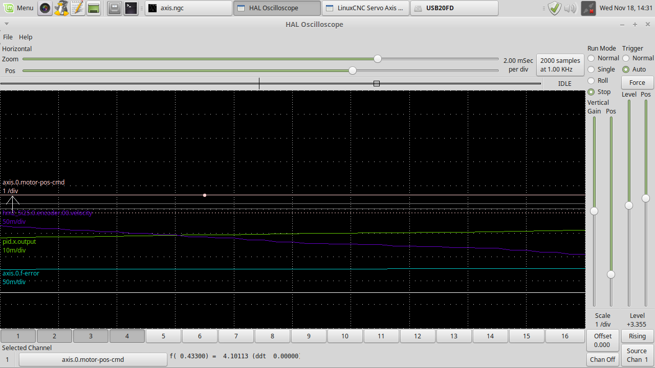
Yeesh, that's a mess. Is that P setting P=111 or P=0.111?
You triggered off of the velocity feedback not the velocity command. For Linuxcnc ver 2.7 the x-axis would be hal pin "axis.0.joint-vel-cmd". The plot of it should produce a nice semitropical trapezoid for a short move.
But regardless, It looks to me that something is backwards. Either the output scale or the direction of the servo amp or something. Because the encoder velocity seems to be doing the opposite of the PID output, when the PID output is negative, the encoder velocity goes positive.
Is there a jumper of dip switch that changes the feedback direction? try flipping that.
Last edit: 5 years 11 months ago by Todd Zuercher.
The following user(s) said Thank You: new2linux
Please Log in or Create an account to join the conversation.
- new2linux
- Offline
- Platinum Member
-
Less
More
- Posts: 711
- Thank you received: 9
5 years 11 months ago - 5 years 11 months ago #189888
by new2linux
Replied by new2linux on topic Replacing Advanced Motion Controls "brush type 12A8 with "Axcent" amplifier
Todd, Many, many thanks!! P= 0.111; I will reset trigger just after sending this reply. You asked about a way to change "jumper of dip switch that changes the feedback direction" this is on the driver I should be investigating?
many thanks!
Edit: Attached are the pic of same settings. P;I, etc (look careful at trace settings!, I had to tweak scale between pics). In the .ini file, the f-errors are still wide open. One of the pics is the beginning of a move, the other is at the end of different move of table, but same settings.
Many thanks!


Last edit: 5 years 11 months ago by new2linux. Reason: Pic
Please Log in or Create an account to join the conversation.
- new2linux
- Offline
- Platinum Member
-
Less
More
- Posts: 711
- Thank you received: 9
5 years 11 months ago - 5 years 11 months ago #189918
by new2linux
Replied by new2linux on topic Replacing Advanced Motion Controls "brush type 12A8 with "Axcent" amplifier
Todd, Many thanks. Attached are a few pics of the tuning with (SW1-6-OFF). This may do what you have asked about, I am not completely shore.
Pic sw1-6off1 is P 0.111; I 0.0; D .01; FF1 .001; FF2 .0001; DEADBAND .000001

Pic sw1-6 is P 0.107; I .01; D .001; FF1 .01; FF2 .001555; DEADBAND .0155

I have asked AMC about your question: Is there a dip switch that changes the feedback direction? SW1-6 goes to off.
this was the response: The fact that the drive is moving the motors in the correct direction for a given command, and that they are not running away means that the encoders are working correctly with the drive.
That makes me wonder if the encoder signal is reversed at the controller side, but I don't know anything about the Linux controller so I don't know how it connects.
Many thanks!
Edit: Referring to the NEW diagram attached, showing GND attached from TB3 (location 3 GND) to the drive pin 11? The diagram is not clear on the AMC (P1) connection, the pins used are pin 4 (+Ref IN); pin 5 (-Ref IN); pin 6 (Encoder B IN); pin 7 (Encoder A IN); pin 9 (INHIBIT/ENABLE); & pin 11 GND.
Edit: The "FERROR & MIN_ERROR" still has wide tolerance.
Pic sw1-6off1 is P 0.111; I 0.0; D .01; FF1 .001; FF2 .0001; DEADBAND .000001
Pic sw1-6 is P 0.107; I .01; D .001; FF1 .01; FF2 .001555; DEADBAND .0155
I have asked AMC about your question: Is there a dip switch that changes the feedback direction? SW1-6 goes to off.
this was the response: The fact that the drive is moving the motors in the correct direction for a given command, and that they are not running away means that the encoders are working correctly with the drive.
That makes me wonder if the encoder signal is reversed at the controller side, but I don't know anything about the Linux controller so I don't know how it connects.
Many thanks!
Edit: Referring to the NEW diagram attached, showing GND attached from TB3 (location 3 GND) to the drive pin 11? The diagram is not clear on the AMC (P1) connection, the pins used are pin 4 (+Ref IN); pin 5 (-Ref IN); pin 6 (Encoder B IN); pin 7 (Encoder A IN); pin 9 (INHIBIT/ENABLE); & pin 11 GND.
Edit: The "FERROR & MIN_ERROR" still has wide tolerance.
Last edit: 5 years 11 months ago by new2linux. Reason: To add complete wiring diagram, add FERROR & MIN_ERROR comment.Edit; add diagran with GND
Please Log in or Create an account to join the conversation.
Time to create page: 0.178 seconds