- Hardware & Machines
- CNC Machines
- Milling Machines
- Replacing Advanced Motion Controls "brush type 12A8 with "Axcent" amplifier
Replacing Advanced Motion Controls "brush type 12A8 with "Axcent" amplifier
- new2linux
- Offline
- Platinum Member
-

Less
More
- Posts: 711
- Thank you received: 9
13 Oct 2020 15:54 #185995
by new2linux
Replied by new2linux on topic Replacing Advanced Motion Controls "brush type 12A8 with "Axcent" amplifier
Many thanks, OT-CNC!! I have reached out to the people at US Digital, gave a pic of the end of encoder and motor data sheet, but still need some of the information below. I have 2 low power power supplies in cabinet, 1 of them I can read, says 24 VDC and leads go to 7i77 card at the Orange location in pic. The other small power supply I cannot read but I believe the leads go to the very right hand end of the pic and makes connection (I do not think this pic shows the location).
The pin out
The power supply voltage to the encoder
The signal output type from the encoder
The signal out voltage level from the encoder
From OT-CNC: "What are you doing with the original Track Encoder, the table mounted unit? What count was that?" All that is gone, if I thought it was of interested I would of saved it?
many thanks
Please Log in or Create an account to join the conversation.
- OT-CNC
- Offline
- Platinum Member
-
Less
More
- Posts: 617
- Thank you received: 75
13 Oct 2020 16:24 #185999
by OT-CNC
Replied by OT-CNC on topic Replacing Advanced Motion Controls "brush type 12A8 with "Axcent" amplifier
If it's a TTL level encoder it's 5v. That's what the 7i77 reads. The large orange connector on that board is the field voltage connection and is your 24v, used for limits, home switches etc. The encoders operate on 5v. You power the encoders from the 5v on the 7i77 encoder connector.
Make sure you follow the mesa manual on jumper selections as you don't want to power the 5v twice. It either gets power from the main card, 5i25 etc or external. Not both. I assume you already know that since you can read in the encoder...
Make sure you follow the mesa manual on jumper selections as you don't want to power the 5v twice. It either gets power from the main card, 5i25 etc or external. Not both. I assume you already know that since you can read in the encoder...
The following user(s) said Thank You: new2linux
Please Log in or Create an account to join the conversation.
- Todd Zuercher
-

- Online
- Platinum Member
-
Less
More
- Posts: 4745
- Thank you received: 1454
13 Oct 2020 17:16 #186002
by Todd Zuercher
Replied by Todd Zuercher on topic Replacing Advanced Motion Controls "brush type 12A8 with "Axcent" amplifier
You shouldn't need another encoder. Why, do you think there is something wrong with your encoder you have?
Did you try connecting the A,B and ground from the encoder to the servo drive? Simply run a few wires from the terminals those wires connect to on the 7i77 over to the drive. I didn't suggest it before because I wasn't sure if it was a good or bad idea, but I have heard of others doing it. I had hoped someone like Peter would chime in and say yes that is ok or no this is how you should connect it. (but the geniuses have been conspicuously silent on the subject.)
Did you try connecting the A,B and ground from the encoder to the servo drive? Simply run a few wires from the terminals those wires connect to on the 7i77 over to the drive. I didn't suggest it before because I wasn't sure if it was a good or bad idea, but I have heard of others doing it. I had hoped someone like Peter would chime in and say yes that is ok or no this is how you should connect it. (but the geniuses have been conspicuously silent on the subject.)
The following user(s) said Thank You: new2linux
Please Log in or Create an account to join the conversation.
- new2linux
- Offline
- Platinum Member
-
Less
More
- Posts: 711
- Thank you received: 9
13 Oct 2020 17:44 - 13 Oct 2020 18:43 #186006
by new2linux
Replied by new2linux on topic Replacing Advanced Motion Controls "brush type 12A8 with "Axcent" amplifier
Todd, Many thanks!! This is from earlier post: When I tested by swapping (x axis encoder and power cable at the back of cabinet) with (y axis encoder and power cable at the back of cabinet) in addition to trying to tune this (use "test" & "cancel" after each change) axis as well. I have saved a file for setup axis x and a 2nd file for y axis. Todd, I just read your post.
I am tiring to tease out the issue, this is what I have tried. I had spent a lot of time over the weekend tiring to duplicate a screen shot from earlier tuning. The only way close is the swap. I am not completely shore.
OT-CNC, Many thanks! I have not tried your "look for a clean square wave coming from the encoder." post yet! OT-CNC, The attached pics are what axis x & axis y look like when the power supply is on, the drives are not engaged, the corresponding, x axis or y axis hal scope is used as to set for pic. Some of the gains were up to show detail. I did not see square wave, but not shore of set up.
many thanks
Last edit: 13 Oct 2020 18:43 by new2linux. Reason: Add pics
Please Log in or Create an account to join the conversation.
- new2linux
- Offline
- Platinum Member
-
Less
More
- Posts: 711
- Thank you received: 9
13 Oct 2020 19:25 #186012
by new2linux
This is to test out the 7i77 circuity? If I understand attach jumpers from where the x axis encoder attaches to 7i77 (these are the very same seen in the pic coming from the encoder, except the attachment point is the 7i77 PCB). Attach other end of jumper to the AMC drive at P1 (Pins 4 & 5)? See P1 connector attachment (page 4 of 9).
Many thanks!
Replied by new2linux on topic Replacing Advanced Motion Controls "brush type 12A8 with "Axcent" amplifier
Did you try connecting the A,B and ground from the encoder to the servo drive? Simply run a few wires from the terminals those wires connect to on the 7i77 over to the drive. I didn't suggest it before because I wasn't sure if it was a good or bad idea, but I have heard of others doing it. I had hoped someone like Peter would chime in and say yes that is ok or no this is how you should connect it. (but the geniuses have been conspicuously silent on the subject.)
This is to test out the 7i77 circuity? If I understand attach jumpers from where the x axis encoder attaches to 7i77 (these are the very same seen in the pic coming from the encoder, except the attachment point is the 7i77 PCB). Attach other end of jumper to the AMC drive at P1 (Pins 4 & 5)? See P1 connector attachment (page 4 of 9).
Many thanks!
Please Log in or Create an account to join the conversation.
- OT-CNC
- Offline
- Platinum Member
-
Less
More
- Posts: 617
- Thank you received: 75
13 Oct 2020 19:55 #186014
by OT-CNC
Replied by OT-CNC on topic Replacing Advanced Motion Controls "brush type 12A8 with "Axcent" amplifier
Just to be clear, the "jumpers" that I was referring to are the small black plastic bridges on the 7i77 that can be moved to configure different settings. Such as the power options. Set those based on the manual.
I think you are referring to the wires going to the terminal blocks as jumpers correct? We are suggesting to connecting an additional set of wires from 7i77 A and B to A (pin7) and B (pin 6) on the AMC. You may need to share ground for it to work? PCW would know.
I don't know why you would connect the encoder to pin 4 and 5? Those are your analog inputs. GND and Aout from the tb5 connector go to there.
Last, if you make up a wiring harness use shielded and twisted pair wiring if you can. Connect the shield drain on one end only, the control cabinet star ground location.
The following user(s) said Thank You: new2linux
Please Log in or Create an account to join the conversation.
- Todd Zuercher
-
- Online
- Platinum Member
-
Less
More
- Posts: 4745
- Thank you received: 1454
13 Oct 2020 20:04 #186015
by Todd Zuercher
Replied by Todd Zuercher on topic Replacing Advanced Motion Controls "brush type 12A8 with "Axcent" amplifier
This is to add encoder feedback to the drive so it can operate in velocity mode. The encoder can be used for both the position feedback to Linuxcnc and the velocity feedback to the drive (if you connect it to both).
The following user(s) said Thank You: new2linux
Please Log in or Create an account to join the conversation.
- new2linux
- Offline
- Platinum Member
-
Less
More
- Posts: 711
- Thank you received: 9
13 Oct 2020 20:13 - 15 Oct 2020 14:28 #186017
by new2linux
Replied by new2linux on topic Replacing Advanced Motion Controls "brush type 12A8 with "Axcent" amplifier
OT-CNC, Thanks! My poor pick of words, ok jumper are very specific term, I will be careful in the future. I am thinking temporary, just to evaluate a test. I want to get it correct, just need some time to ponder, maybe.I can see in the last "look for a clean square wave coming from the encoder" in recent post that the "HandWheelY.png" is closer than the handwheelxpng pic to being a square shape. Is this a good test for the encoder? Am I looking / tracing the correct pins, as to get usable knowledge? If there is specific question about setup that only the A-M-C may know, and if I can understand the question well enough to describe to the tech, I may get an answer.Many thanks
Edit1: Todd Many Thanks!!! Just read your post, I understand why now, I will reread and try to run temp wires, to see if an additional encoder feedback can be arranged. It seems to me the plug has wires that were never used or went nowhere. I need to get fresh look at the set of wires coming back to electrical cabinet as to where they go. Many, many thanks!!
Edit2: The pic (this pic too large to load) of the back of the pass through, there are several wires going all to the same lead, this is the shielding of the cable going to the encoder on the back of motor for that axis. The wiring diagram shows the back of that (x=no lead in that location) plug with numbers corresponding to the colors on the leads in the pic of the encoder in post (11 Oct 2020 15:00 #185720). The other end of diagram shows the placement of leads at the 7i77 card TB3 location,(x=no lead in that location).
Many thanks to all the kind and talented people that make this place work so well.
I warmly welcome thoughtful help, or please point me in the direction to search.
Many, many thanks!
Last edit: 15 Oct 2020 14:28 by new2linux. Reason: Edit1: Todd responce: Edit2 add pic(plug pic would not load)
Please Log in or Create an account to join the conversation.
- new2linux
- Offline
- Platinum Member
-
Less
More
- Posts: 711
- Thank you received: 9
14 Oct 2020 14:24 - 14 Oct 2020 20:28 #186094
by new2linux
Todd, Thanks for your help. I have reviewed my emails with A-M-C techs; this is a response from an earlier question.
This is the email:
"2.6.4 Encoder Velocity Mode In Encoder Velocity Mode, the input command controls the motor
velocity, with the frequency of the encoder pulses closing the velocity loop. An analog velocity
monitor output allows observation of the actual motor speed through a kHz/V scaling factor
found on the drive datasheet. The voltage value read at the velocity monitor output can
be used to determine the motor RPM through the scaling factor. See “Velocity Monitor Output” on
page 41 for the motor RPM equation.
Note
The high resolution of motor mounted encoders allows for excellent
velocity control and smooth motion at all speeds. Encoder Velocity
Mode should be used for applications requiring precise and accurate
velocity control, and is especially useful
I also read this:
2.5.2 Incremental Encoder
Analog servo drives that use encoder feedback utilize two single-ended
or differential incremental encoder inputs for velocity control. The encoder provides
incremental position feedback that can be extrapolated into very precise velocity
information. The encoder signals are read as "pulses" that the drive uses to essentially keep track of
the motor’s position and direction of rotation. Based on the speed and order in which these pulses
It seems to me I need "two single-ended" or "differential incremental
encoder" inputs for velocity control."
This is response from A-M-C:
"The AB15A100 only accepts a single ended encoder input. If you do have a differential encoder, you can just use the A+ and B+ lines and don't connect the /A and /B signals. It will still work as a single ended signal, you just won't have the benefits of a differential signal."
The manual is too large to attach. Edit: To have access to the A-M-C manuals you need password.
2nd Edit: I have approached AMC with the hope of an explanation and this is the response: If you have a differential encoder you only need to connect the A+ and B+ signals and it will work just fine.
It appears both will work. I am not shore of some of the following that is required to order encoder.
The pin out
The power supply voltage to the encoder (this is 5 VDC)
The signal output type from the encoder
The signal out voltage level from the encoder
The resolution or CPR of the encoder (2000)
many thanks!
Replied by new2linux on topic Replacing Advanced Motion Controls "brush type 12A8 with "Axcent" amplifier
This is to add encoder feedback to the drive so it can operate in velocity mode. The encoder can be used for both the position feedback to Linuxcnc and the velocity feedback to the drive (if you connect it to both).
Todd, Thanks for your help. I have reviewed my emails with A-M-C techs; this is a response from an earlier question.
This is the email:
"2.6.4 Encoder Velocity Mode In Encoder Velocity Mode, the input command controls the motor
velocity, with the frequency of the encoder pulses closing the velocity loop. An analog velocity
monitor output allows observation of the actual motor speed through a kHz/V scaling factor
found on the drive datasheet. The voltage value read at the velocity monitor output can
be used to determine the motor RPM through the scaling factor. See “Velocity Monitor Output” on
page 41 for the motor RPM equation.
Note
The high resolution of motor mounted encoders allows for excellent
velocity control and smooth motion at all speeds. Encoder Velocity
Mode should be used for applications requiring precise and accurate
velocity control, and is especially useful
I also read this:
2.5.2 Incremental Encoder
Analog servo drives that use encoder feedback utilize two single-ended
or differential incremental encoder inputs for velocity control. The encoder provides
incremental position feedback that can be extrapolated into very precise velocity
information. The encoder signals are read as "pulses" that the drive uses to essentially keep track of
the motor’s position and direction of rotation. Based on the speed and order in which these pulses
It seems to me I need "two single-ended" or "differential incremental
encoder" inputs for velocity control."
This is response from A-M-C:
"The AB15A100 only accepts a single ended encoder input. If you do have a differential encoder, you can just use the A+ and B+ lines and don't connect the /A and /B signals. It will still work as a single ended signal, you just won't have the benefits of a differential signal."
The manual is too large to attach. Edit: To have access to the A-M-C manuals you need password.
2nd Edit: I have approached AMC with the hope of an explanation and this is the response: If you have a differential encoder you only need to connect the A+ and B+ signals and it will work just fine.
It appears both will work. I am not shore of some of the following that is required to order encoder.
The pin out
The power supply voltage to the encoder (this is 5 VDC)
The signal output type from the encoder
The signal out voltage level from the encoder
The resolution or CPR of the encoder (2000)
many thanks!
Last edit: 14 Oct 2020 20:28 by new2linux. Reason: password for manuals 2nd Edit:amc responce
Please Log in or Create an account to join the conversation.
- new2linux
- Offline
- Platinum Member
-
Less
More
- Posts: 711
- Thank you received: 9
19 Oct 2020 18:18 - 06 Nov 2020 21:15 #186599
by new2linux
Replied by new2linux on topic Replacing Advanced Motion Controls "brush type 12A8 with "Axcent" amplifier
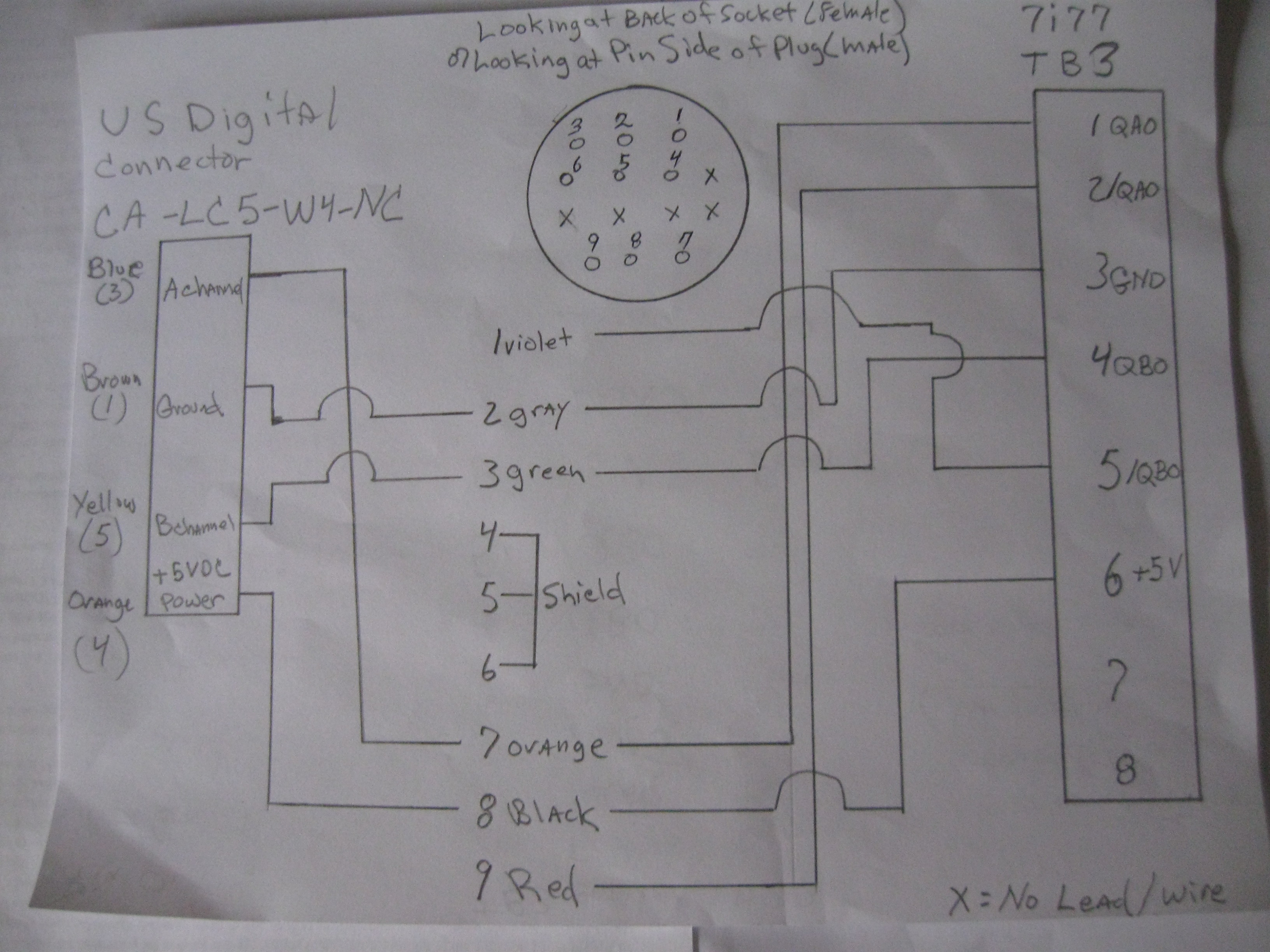
I offer my many thanks to all of those people who make this forum work so well. I have reviewed several documents including the 7i77 manual. As per the manual and the tech at USDigital this diagram I believe is accurate to fit the application. The jumpers on 7i77 are moved to the left, which means board is configured to receive a single ended encoder signal (based on page 3 of the 7177 manual. I believe the motor listed at this prior post: (27 Sep 2020 15:11 - 28 Sep 2020 16:07 #18398) requires encoders described below to work property.
EM1-2-500-N
HUBDISK-2-500-500-NE
CA-LC5-W4-NC-1
You can find mechanical drawings and pricing for each item on our website here:
encoder:
www.usdigital.com/products/encoders/incr.../modules/EM1-2-500-N
encoder wheel:
www.usdigital.com/products/encoders/incr...HUBDISK-2-500-500-NE
Cable&Connector
www.usdigital.com/products/accessories/cables/CA-LC5-W4-NC-1
The diagram shows the 7I77 (TB3) on the right side, going to the original prototrak plug (the round plug, numbered 1 to 9) and the USDigital CA-LC5-W4-NC-1 to the left side of screen.
Many thanks,
Edit: The new (USDigital) encoders are installed. Jumper set to the left on TB3. The DRO does not function. What should I be looking for? Status LEDs look correct.
All help is warmly welcomed.
Last edit: 06 Nov 2020 21:15 by new2linux. Reason: typo: 2nd edit; detailed diagram: edit01 correct encoder wheel hole size
Please Log in or Create an account to join the conversation.
Moderators: piasdom
- Hardware & Machines
- CNC Machines
- Milling Machines
- Replacing Advanced Motion Controls "brush type 12A8 with "Axcent" amplifier
Time to create page: 0.182 seconds