×
Forum Header
Home switches wiring / setup
- remon_v
- Offline
- Premium Member
-

Less
More
- Posts: 97
- Thank you received: 7
12 Feb 2022 22:07 - 12 Feb 2022 22:09 #234663
by remon_v
Replied by remon_v on topic Home switches wiring / setup
Not sure what you mean… do you mean ‘Hal show’? To see is the pin triggers? That’s a good one, haven’t tried that…
Last edit: 12 Feb 2022 22:09 by remon_v.
Please Log in or Create an account to join the conversation.
- Clive S
- Offline
- Platinum Member
-

Less
More
- Posts: 2204
- Thank you received: 486
12 Feb 2022 22:22 #234664
by Clive S
Yes its a good tool there is hal show and watch you can pick the pins and signal you need to look at.
Its worth spending a bit of time with it.
Its very hard when trying to help people when not sure of their knowledge or language.
I am not a pro by any means but have built more that 10 machines several with gantries using pports and messa cards.
It might help if you can draw a diagram of how you have it wired.
Just start with one gantry only and forget the others for now.
Replied by Clive S on topic Home switches wiring / setup
Not sure what you mean… do you mean ‘Hal show’? To see is the pin triggers? That’s a good one, haven’t tried that…
Yes its a good tool there is hal show and watch you can pick the pins and signal you need to look at.
Its worth spending a bit of time with it.
Its very hard when trying to help people when not sure of their knowledge or language.
I am not a pro by any means but have built more that 10 machines several with gantries using pports and messa cards.
It might help if you can draw a diagram of how you have it wired.
Just start with one gantry only and forget the others for now.
Please Log in or Create an account to join the conversation.
- remon_v
- Offline
- Premium Member
-
Less
More
- Posts: 97
- Thank you received: 7
13 Feb 2022 10:16 - 13 Feb 2022 10:35 #234677
by remon_v
Replied by remon_v on topic Home switches wiring / setup
Thanks, the HAL Show/watch is a good one, I tested it out last night.
Everything seems to work fine, except the homing switches. Even in the HAL watch it doesn’t give me a signal.
So I must be wiring it up wrong…. I connect the NO pin to the P10 and the COM to the GND
Everything seems to work fine, except the homing switches. Even in the HAL watch it doesn’t give me a signal.
So I must be wiring it up wrong…. I connect the NO pin to the P10 and the COM to the GND
Last edit: 13 Feb 2022 10:35 by remon_v.
Please Log in or Create an account to join the conversation.
- tommylight
-

- Online
- Moderator
-

Less
More
- Posts: 21644
- Thank you received: 7394
13 Feb 2022 10:19 #234678
by tommylight
Replied by tommylight on topic Home switches wiring / setup
Where is the COM from the switch connected ?
Please Log in or Create an account to join the conversation.
- remon_v
- Offline
- Premium Member
-
Less
More
- Posts: 97
- Thank you received: 7
13 Feb 2022 10:34 #234679
by remon_v
Replied by remon_v on topic Home switches wiring / setup
The COM is connected to ground (GND)
Please Log in or Create an account to join the conversation.
- Clive S
- Offline
- Platinum Member
-
Less
More
- Posts: 2204
- Thank you received: 486
13 Feb 2022 11:30 #234681
by Clive S
I don't think you have said what BOB you are working with. if it is the standard china one with the blue relay
It will need powering with 5V and 12-24V otherwise the inputs won't work.
So can you give a link to the BOB and how you have that wired
Replied by Clive S on topic Home switches wiring / setup
The COM is connected to ground (GND)
I don't think you have said what BOB you are working with. if it is the standard china one with the blue relay
It will need powering with 5V and 12-24V otherwise the inputs won't work.
So can you give a link to the BOB and how you have that wired
Please Log in or Create an account to join the conversation.
- remon_v
- Offline
- Premium Member
-
Less
More
- Posts: 97
- Thank you received: 7
13 Feb 2022 11:49 #234682
by remon_v
Replied by remon_v on topic Home switches wiring / setup
Yes the 5 Axis BOB with the relay.
I’ve connected USB and a 24V power supply.
Here’s a photo…
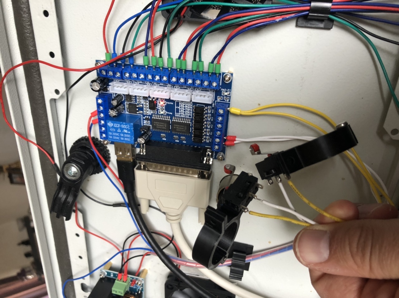
I’ve connected USB and a 24V power supply.
Here’s a photo…
Attachments:
Please Log in or Create an account to join the conversation.
- Clive S
- Offline
- Platinum Member
-
Less
More
- Posts: 2204
- Thank you received: 486
13 Feb 2022 12:45 - 13 Feb 2022 13:08 #234692
by Clive S
Replied by Clive S on topic Home switches wiring / setup
Are you saying that in halshow looking at the say pin parport.0.pin-10-in does it change from yellow to brown or vice versa ?
Can you check with a meter what volage you get on pin 10 BOB and when the switch is activated
Have to tried connecting the 2 -ve gnd's together. I would remove input 11 until you get input 10 working.
edit
try this: assuming the X is joint 0
net home-x1-y1 <= parport.0.pin-10-in
net home-x1-y1 <= joint.0.home-sw-in
Last edit: 13 Feb 2022 13:08 by Clive S.
Please Log in or Create an account to join the conversation.
- remon_v
- Offline
- Premium Member
-
Less
More
- Posts: 97
- Thank you received: 7
13 Feb 2022 13:37 - 13 Feb 2022 13:44 #234693
by remon_v
Replied by remon_v on topic Home switches wiring / setup
Hal watch… does nothing even when I just connect P10 and configuring like you suggested (just joint 0 / X1)
I’ve measured the voltage, when not triggered it’s 9V. When triggered it’s 0V.
I’ve measured the voltage, when not triggered it’s 9V. When triggered it’s 0V.
Last edit: 13 Feb 2022 13:44 by remon_v.
Please Log in or Create an account to join the conversation.
- Clive S
- Offline
- Platinum Member
-
Less
More
- Posts: 2204
- Thank you received: 486
13 Feb 2022 13:39 #234694
by Clive S
Replied by Clive S on topic Home switches wiring / setup
Did you see my edit ?
Please Log in or Create an account to join the conversation.
Time to create page: 0.198 seconds