Tiny Computer with Printer port
- BigJohnT
-

- Offline
- Administrator
-

- Posts: 7000
- Thank you received: 1176
Thanks
JT
Now done thanks John
Please Log in or Create an account to join the conversation.
- tenaja
- Offline
- Senior Member
-

- Posts: 60
- Thank you received: 5
Please Log in or Create an account to join the conversation.
- tkamsker
- Offline
- Premium Member
-

- Posts: 129
- Thank you received: 5
") -
-My cnc "dealer" did import them directly to austria/Europe
I am working on an VFD Toolchanger configuration fpr 3 or 4 axis Milling machines
And we will then order batches
so i can ask him when he is ordering the next batch if you need / want to
thomas
No i am fighting with spindle orientation
- Please Log in or Create an account to join the conversation.
- ArcEye
- Offline
- Junior Member
-

- Posts: 24
- Thank you received: 758
The o/p removed the link, and the pc has been removed from their web site. The only place I could find it was robotshop or something like that. After all that work, is there going to be a sustainable source?
RoBoard who make it, are a robotics company.
I found it for sale on a UK site and a US site, both of which show stock available, so presume availability for the time being.
www.roboard.com/ncbox-189.html
secure.robotshop.com/roboard-ncbox-189-c...ne-controller-2.html
robosavvy.com/store/product_info.php/products_id/3848
Quite honestly the disk image was more to save me time than anything.
Much easier to provide a package that just works, than try to talk an endless stream of people of varying degrees of Linux knowledge, through a complicated build process.
regards
Please Log in or Create an account to join the conversation.
- tkamsker
- Offline
- Premium Member
-
- Posts: 129
- Thank you received: 5
(Update of status i have one cf with a manual compiled ok kernel and run linuxcnc 2.5.2 fine i had a parport config where i can also conrtol the vfd because of spindel orientation i have bought 8gb cf cards and used your binary package to be compatible ,..
that worked fine as well now i want to use GPIO
i did load down the code and compiled it in it should work
so now my confusion
1) the picture shows 2 times 8 pins
2) your text on tab 3 says you have the gpio as 3 times 8 pins
i tried the example nice but where is the pin ? i understand the masking but not where is which pin ?
so my question
would it be possible to use the "LPT" board "normal" like an lpt board
and on top configure the gpio board as 3 times 8 pins or like the picture says 2 times 8 pins
if i know which pin i can go to the machine and see if spindle orientation "likes" me
-thx
thomas
Please Log in or Create an account to join the conversation.
- ArcEye
- Offline
- Junior Member
-
- Posts: 24
- Thank you received: 758
You will be glad to know it is quite simple, you have been looking at a picture labelled NCBOX-PWM
The picture for the GPIO ports never uploaded for some reason, I think the picture size limit was lower then
So here it is
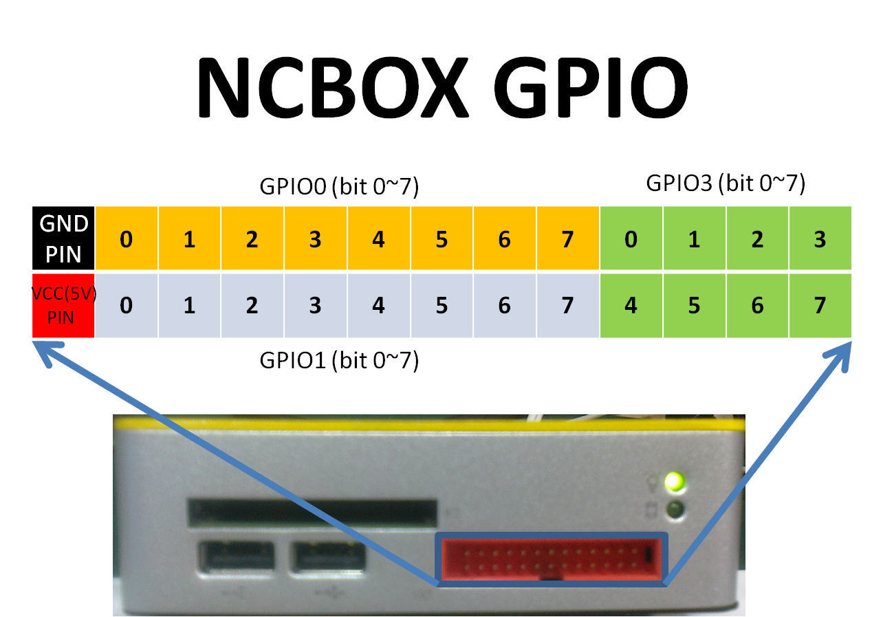
The ports can be set in BIOS but I seem to remember thay are all IN pins by default
regards
Please Log in or Create an account to join the conversation.
- ArcEye
- Offline
- Junior Member
-
- Posts: 24
- Thank you received: 758
have bought 8gb cf cards and used your binary package to be compatible ,..
that worked fine
Thanks for trying it and reporting back, I know it works for me, but needed someone else to confirm
Please Log in or Create an account to join the conversation.
- tkamsker
- Offline
- Premium Member
-
- Posts: 129
- Thank you received: 5
Verry nice thx for the picture ,..
i made yesterday pin 7 to respond
so i was afraid to use try & error for that pins now i am verry happy ,..
Question should i try something for the "audience"
my next steps will be
1) Spindle orientation ( i have an Voltage divider on an 24V conactless switch which i put in one of the pins
2.) Toolchanger carousel
2.1) 2 Relais (24V) for left right and turn on
2.2) 2 24V conactless switches for index and posistion of the turret
2.3) 2 endswitches for Carousel is back or is in front
2.4) 1 Solenoid valve (which will be an 24V Relais
- for test to push Carousel in front position if not powered carousel goes in back position3.) 2 Relais for the spindle operation
4.) 2 Switches to check spindle position
the rest of the pins i will use for Buttons
-so on fr i will work on Spindle orientation
meanwhile i read a lot to see if i use classicladder or write an component for toolchanger
thomas
Which means if anyone want to use that small NCBOX i can try some stuff if needed
in the end of the project
one of the box will go on my turning lathe -> yes i want thread with it
-and the 2nd box will go to the mill with ATC
thomas
Please Log in or Create an account to join the conversation.
- tkamsker
- Offline
- Premium Member
-
- Posts: 129
- Thank you received: 5
I do have your Board now um and running
I managed to use LPT for the normal Stepper configuration VFD and so on,..
I also managed tu use 2 Times 8 Pins of the gpio´s but now i am got stuck
I prepared an Electronic (which is where i am not 100% firm i am mecanic and software developer ,... )
where i use an Inducttive NPN Switch It is an IF71002 ( www.produktinfo.conrad.com/datenblaetter...NKG_I_US_100_DPS.pdf )
It works with 24V like i use the Power for your Board
then i build an Voltage divieder to get the voltage down below 5 V (between 3 and 4.5)
So then i found out that your pin "wants" minus pole to get activated ,..
I tried to reverse that with an BC547 Tranistor but i spend the whole day to day it doesnt work.
So i would love to use my Voltage divider .
Question 1 )
Is there a chance somewhere in the bios for instace (which i searched) to tell the board please use + as logical 1 not minus ?
Then my electronic should work immediatlely
Question 2)
Do i have to buy an PNP Switch instead ?
Question 3)
You developed the board probably you have an recomendation how to tacle that problem
thx
thomas
Please Log in or Create an account to join the conversation.
- ArcEye
- Offline
- Junior Member
-
- Posts: 24
- Thank you received: 758
Pending any reply from Anthony, have you thought of just using the 24v from the inductive proximity switch, to switch a 5v signal of the correct polarity, rather than directly connect.
Found this circuit too
www.cosel.co.jp/en/data/pdf/reverse_polarity.pdf
I'm sure Andy, Jon or PCW will have loads of other ways to do it.
regards
Please Log in or Create an account to join the conversation.