Remora - ethernet NVEM / EC300 / EC500 cnc board
- TimGow
- Offline
- Junior Member
-

Less
More
- Posts: 36
- Thank you received: 3
01 Jan 2024 01:34 #289455
by TimGow
Replied by TimGow on topic Remora - ethernet NVEM / EC300 / EC500 cnc board
Hi Scott,
Thank you for the Baud rate and the latest version, not sure how I was so out of date.
Much appreciated, this is a great project that you've created.
Happy New Year
Thank you for the Baud rate and the latest version, not sure how I was so out of date.
Much appreciated, this is a great project that you've created.
Happy New Year
Please Log in or Create an account to join the conversation.
- TimGow
- Offline
- Junior Member
-
Less
More
- Posts: 36
- Thank you received: 3
01 Jan 2024 17:52 #289487
by TimGow
Replied by TimGow on topic Remora - ethernet NVEM / EC300 / EC500 cnc board
Hello all,
Can you please shed some light on some pyocd output for me? I appreciate any help that you can provide from your experience.
(base) C:\Users\...\Remora-RT1052-cpp-main\Remora-RT1052-cpp-main\Firmware>pyocd flash .\remora-rt1052-3.1.2.bin --target mimxrt1050_quadspi -v
0003413 I Target type is mimxrt1050_quadspi [board]
0003538 I DP IDR = 0x0bd11477 (v1 MINDP rev0) [dap]
0003561 I AHB-AP#0 IDR = 0x04770041 (AHB-AP var4 rev0) [ap]
0003619 I AHB-AP#0 Class 0x1 ROM table #0 @ 0xe00fd000 (designer=00e:NXP part=88c) [rom_table]
0003634 I [0]<e00fe000:ROM class=1 designer=43b:Arm part=4c8> [rom_table]
0003634 I AHB-AP#0 Class 0x1 ROM table #1 @ 0xe00fe000 (designer=43b:Arm part=4c8) [rom_table]
0003647 I [0]<e00ff000:ROM class=1 designer=43b:Arm part=4c7> [rom_table]
0003648 I AHB-AP#0 Class 0x1 ROM table #2 @ 0xe00ff000 (designer=43b:Arm part=4c7) [rom_table]
0003661 I [0]<e000e000:SCS v7-M class=14 designer=43b:Arm part=00c> [rom_table]
0003667 I [1]<e0001000:DWT v7-M class=14 designer=43b:Arm part=002> [rom_table]
0003711 I [2]<e0002000:FPB v7-M class=14 designer=43b:Arm part=00e> [rom_table]
0003718 I [3]<e0000000:ITM v7-M class=14 designer=43b:Arm part=001> [rom_table]
0003731 I [1]<e0041000:ETM M7 class=9 designer=43b:Arm part=975 devtype=13 archid=4a13 devid=0:0:0> [rom_table]
0003742 I [2]<e0042000:CTI class=9 designer=43b:Arm part=906 devtype=14 archid=0000 devid=40800:0:0> [rom_table]
0003754 I [1]<e0040000:TPIU M7 class=9 designer=43b:Arm part=9a9 devtype=11 archid=0000 devid=ca1:0:0> [rom_table]
0003764 I [2]<e0043000:TSGEN class=15 designer=43b:Arm part=101> [rom_table]
0003770 I IMXRT Boot Mode: Internal Boot [target_imxrt]
0003828 I CPU core #0 is Cortex-M7 r1p1 [cortex_m]
0003837 I FPU present: FPv5-D16-M [cortex_m]
0003846 I 4 hardware watchpoints [dwt]
0003855 I 8 hardware breakpoints, 1 literal comparators [fpb]
0003881 I Loading C:\Users\...\Remora-RT1052-cpp-main\Remora-RT1052-cpp-main\Firmware\remora-rt1052-3.1.2.bin [load_cmd]
0004032 I IMXRT Boot Mode: Internal Boot [target_imxrt]
0004039 I IMXRT Boot Device: 0 [target_imxrt]
[==================================================] 100%
0109579 I IMXRT Boot Mode: Internal Boot [target_imxrt]
0109582 I IMXRT Boot Device: 0 [target_imxrt]
0109715 I Erased 393216 bytes (6 sectors), programmed 358656 bytes (1401 pages), skipped 0 bytes (0 pages) at 3.31 kB/s [loader]
Does "programmed 358656 bytes (1401 pages)" suggest success in uploading the firmware to the EC300? These numbers correct?
Is the "0004039 I IMXRT Boot Device: 0 [target_imxrt]" a problem, should there be a Boot Device?
Command 'pyocd list' gives result Target N/A, is pyocd command line "--target mimxrt1050_quadspi" the accepted remedy for a CMSIS-DAP not able to auto-detect the RT1052 in the EC300?
I am not seeing any life through my serial to USB module for feed back when powered on (COM4, Baud 115200).
Which LEDs on the EC300 are illuminated when powered up with valid Remora and no ethernet connected?
Following this pyocd upload I have 3 LEDs on, one by the 24V, one by the COM+ and one by the ethernet socket; is this correct?
That's several questions, I appreciate you reading.
Please Log in or Create an account to join the conversation.
- scotta
-
 Topic Author
- Offline
- Platinum Member
-

Less
More
- Posts: 959
- Thank you received: 489
04 Jan 2024 23:15 #289813
by scotta
Replied by scotta on topic Remora - ethernet NVEM / EC300 / EC500 cnc board
Looks like you have successfully programmed the board. Best to have Ethernet connected as the boot process will hang waiting for the network. Without the network cable attached I could reproduce what you are seeing with no serial output and the 3 LEDs on. But most often getting to
Remora RT1052 starting
Initializing PHY...
Remora RT1052 starting
Initializing PHY...
The following user(s) said Thank You: TimGow
Please Log in or Create an account to join the conversation.
- beauxnez
- Offline
- Premium Member
-

Less
More
- Posts: 149
- Thank you received: 10
05 Jan 2024 07:29 - 05 Jan 2024 07:30 #289833
by beauxnez
Replied by beauxnez on topic Remora - ethernet NVEM / EC300 / EC500 cnc board
bonjour
j'ai reçu la carte nvem, j'ai commandé une V2.1 et j'ai reçu une V5
la puce est une RT1052
est-ce qu'une stm32 est meilleure ?
j'ai reçu la carte nvem, j'ai commandé une V2.1 et j'ai reçu une V5
la puce est une RT1052
est-ce qu'une stm32 est meilleure ?
Last edit: 05 Jan 2024 07:30 by beauxnez.
Please Log in or Create an account to join the conversation.
- scotta
-
Topic Author
- Offline
- Platinum Member
-
Less
More
- Posts: 959
- Thank you received: 489
05 Jan 2024 07:40 #289834
by scotta
Replied by scotta on topic Remora - ethernet NVEM / EC300 / EC500 cnc board
The RT1052 is far more capable and can use the latest firmware.
Le RT1052 est bien plus performant et peut utiliser le dernier firmware.
Le RT1052 est bien plus performant et peut utiliser le dernier firmware.
Please Log in or Create an account to join the conversation.
- beauxnez
- Offline
- Premium Member
-
Less
More
- Posts: 149
- Thank you received: 10
05 Jan 2024 08:01 #289835
by beauxnez
Replied by beauxnez on topic Remora - ethernet NVEM / EC300 / EC500 cnc board
ok I will follow your video
thank you for your work
thank you for your work
Please Log in or Create an account to join the conversation.
- TimGow
- Offline
- Junior Member
-
Less
More
- Posts: 36
- Thank you received: 3
05 Jan 2024 09:48 #289843
by TimGow
All the work much appreciated.
Replied by TimGow on topic Remora - ethernet NVEM / EC300 / EC500 cnc board
Scott, thank you for interpreting the pyocd output and LEDs ... onto the RPi4 now.Looks like you have successfully programmed the board. Best to have Ethernet connected as the boot process will hang waiting for the network. Without the network cable attached I could reproduce what you are seeing with no serial output and the 3 LEDs on. But most often getting to
Remora RT1052 starting
Initializing PHY...
All the work much appreciated.
Please Log in or Create an account to join the conversation.
- beauxnez
- Offline
- Premium Member
-
Less
More
- Posts: 149
- Thank you received: 10
05 Jan 2024 12:32 #289857
by beauxnez
Replied by beauxnez on topic Remora - ethernet NVEM / EC300 / EC500 cnc board
I soldered the wires on the nvem V5
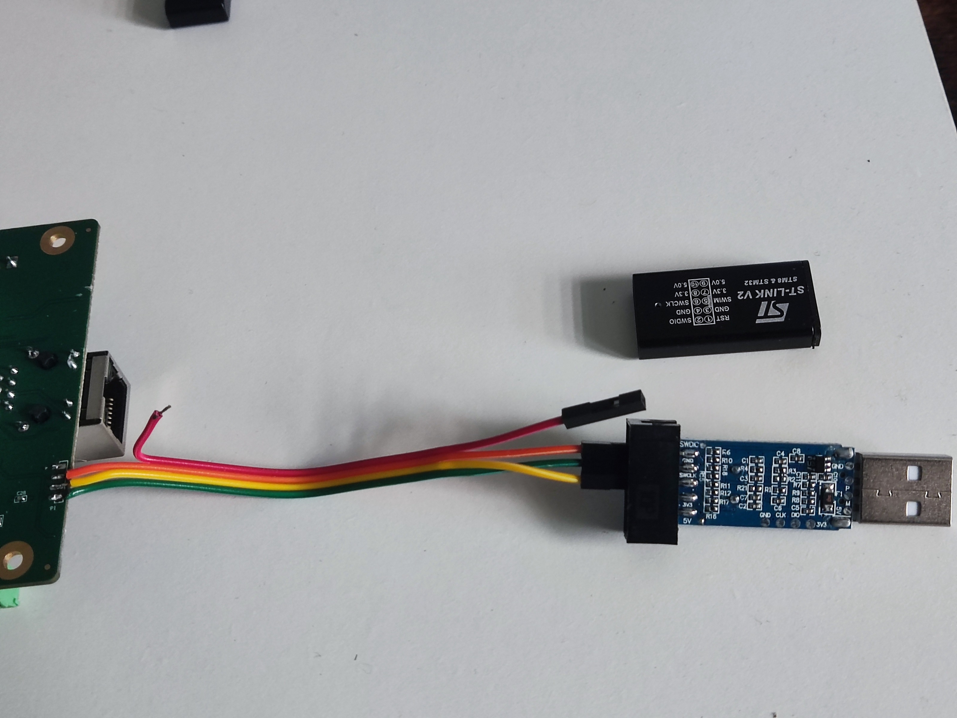
is the wiring good I don't want them all to be burnt
is the wiring good I don't want them all to be burnt
Attachments:
Please Log in or Create an account to join the conversation.
- TimGow
- Offline
- Junior Member
-
Less
More
- Posts: 36
- Thank you received: 3
05 Jan 2024 16:39 #289880
by TimGow
Replied by TimGow on topic Remora - ethernet NVEM / EC300 / EC500 cnc board
Hi beauxnez,
I'm guessing that you are needing to know any difference between NVEM V2 and V5.
NVEM V2 SWD connection is shown here: 15 Jan 2022 03:42 #231852
I see that your V5 has an additional underside component or solder joint inboard from your green wire connection, so there are differences and reason to verify the order of the SWDIO, SWCLK & GND.
Please Log in or Create an account to join the conversation.
- beauxnez
- Offline
- Premium Member
-
Less
More
- Posts: 149
- Thank you received: 10
05 Jan 2024 21:18 - 05 Jan 2024 21:31 #289904
by beauxnez
Replied by beauxnez on topic Remora - ethernet NVEM / EC300 / EC500 cnc board
I just have the SWDIO, SWCLK and GND to connect to the SWDIO, SWCLK and GND of the programming key?
no 5v or 3.3v?
out of the 150 pages is there one that explains the procedure for flashing? a v5 version, v2 looks simpler flashed
no 5v or 3.3v?
out of the 150 pages is there one that explains the procedure for flashing? a v5 version, v2 looks simpler flashed
Last edit: 05 Jan 2024 21:31 by beauxnez.
Please Log in or Create an account to join the conversation.
Time to create page: 0.658 seconds