Remora - ethernet NVEM / EC300 / EC500 cnc board
- cakeslob
- Offline
- Platinum Member
-

Less
More
- Posts: 926
- Thank you received: 278
06 Apr 2025 16:32 #325821
by cakeslob
Replied by cakeslob on topic Remora - ethernet NVEM / EC300 / EC500 cnc board
post your config.txt
The following user(s) said Thank You: jenkinson8
Please Log in or Create an account to join the conversation.
- jenkinson8
- Offline
- New Member
-

Less
More
- Posts: 10
- Thank you received: 1
07 Apr 2025 02:25 #325851
by jenkinson8
Replied by jenkinson8 on topic Remora - ethernet NVEM / EC300 / EC500 cnc board
Sure, when I did this, I uploaded the unmodified
nvem-full-config.txt
- from the Remora repo.
Reading the upload script, it looks like it makes a copy of what I feed into it and writes it to this config.txt file? Comparing the two documents showed them as identical.
Contents of the file to sense check:
Something else worth mentioning, I had read that the 4/5/6 axis boards used the same hardware, and that Remora doesn't care which version of the board you get. I bought a 4 axis version as the others were more expensive for seemingly no value add if used with Remora. I did use my multimeter and could trace the 5 and 6 axis step/dir pins back to what looks like a buffer IC at least. Hopefully I don't have some later version of the board that has additional locks in place.
Reading the upload script, it looks like it makes a copy of what I feed into it and writes it to this config.txt file? Comparing the two documents showed them as identical.
Contents of the file to sense check:
{
"Board": "NVEM",
"Modules":[
{
"Thread": "Base",
"Type": "Stepgen",
"Comment": "X - Joint 0 step generator",
"Joint Number": 0,
"Step Pin": "PE_15",
"Direction Pin": "PE_14"
},
{
"Thread": "Base",
"Type": "Stepgen",
"Comment": "Y - Joint 1 step generator",
"Joint Number": 1,
"Step Pin": "PE_13",
"Direction Pin": "PE_12"
},
{
"Thread": "Base",
"Type": "Stepgen",
"Comment": "Z - Joint 2 step generator",
"Joint Number": 2,
"Step Pin": "PE_11",
"Direction Pin": "PE_10"
},
{
"Thread": "Base",
"Type": "Stepgen",
"Comment": "A - Joint 3 step generator",
"Joint Number": 3,
"Step Pin": "PE_9",
"Direction Pin": "PE_8"
},
{
"Thread": "Base",
"Type": "Stepgen",
"Comment": "B - Joint 4 step generator",
"Joint Number": 4,
"Step Pin": "PE_7",
"Direction Pin": "PA_8"
},
{
"Thread": "Base",
"Type": "Stepgen",
"Comment": "C - Joint 5 step generator",
"Joint Number": 5,
"Step Pin": "PA_5",
"Direction Pin": "PA_6"
},
{
"Thread": "Servo",
"Type": "Digital Pin",
"Comment": "FHA",
"Pin": "PD_12",
"Mode": "Input",
"Data Bit": 0,
"Invert": "True"
},
{
"Thread": "Servo",
"Type": "Digital Pin",
"Comment": "FHB",
"Pin": "PD_13",
"Mode": "Input",
"Data Bit": 1,
"Invert": "True"
},
{
"Thread": "Servo",
"Type": "Digital Pin",
"Comment": "SRO",
"Pin": "PB_14",
"Mode": "Input",
"Data Bit": 2,
"Invert": "True"
},
{
"Thread": "Servo",
"Type": "Digital Pin",
"Comment": "SJR",
"Pin": "PB_15",
"Mode": "Input",
"Data Bit": 3,
"Invert": "True"
},
{
"Thread": "Servo",
"Type": "Digital Pin",
"Comment": "STOP",
"Pin": "PD_8",
"Mode": "Input",
"Data Bit": 4,
"Invert": "False"
},
{
"Thread": "Servo",
"Type": "Digital Pin",
"Comment": "PROBE",
"Pin": "PD_9",
"Mode": "Input",
"Data Bit": 5,
"Invert": "True"
},
{
"Thread": "Servo",
"Type": "Digital Pin",
"Comment": "INP3",
"Pin": "PD_10",
"Mode": "Input",
"Data Bit": 6,
"Invert": "True"
},
{
"Thread": "Servo",
"Type": "Digital Pin",
"Comment": "INP4",
"Pin": "PD_11",
"Mode": "Input",
"Data Bit": 7,
"Invert": "True"
},
{
"Thread": "Servo",
"Type": "Digital Pin",
"Comment": "INP5",
"Pin": "PD_14",
"Mode": "Input",
"Data Bit": 8,
"Invert": "True"
},
{
"Thread": "Servo",
"Type": "Digital Pin",
"Comment": "INP6",
"Pin": "PD_15",
"Mode": "Input",
"Data Bit": 9,
"Invert": "True"
},
{
"Thread": "Servo",
"Type": "Digital Pin",
"Comment": "INP7",
"Pin": "PC_6",
"Mode": "Input",
"Data Bit": 10,
"Invert": "True"
},
{
"Thread": "Servo",
"Type": "Digital Pin",
"Comment": "INP8",
"Pin": "PC_7",
"Mode": "Input",
"Data Bit": 11,
"Invert": "True"
},
{
"Thread": "Servo",
"Type": "Digital Pin",
"Comment": "INP9",
"Pin": "PC_8",
"Mode": "Input",
"Data Bit": 12,
"Invert": "True"
},
{
"Thread": "Servo",
"Type": "Digital Pin",
"Comment": "INP10",
"Pin": "PC_9",
"Mode": "Input",
"Data Bit": 13,
"Invert": "True"
},
{
"Thread": "Servo",
"Type": "Digital Pin",
"Comment": "INP11",
"Pin": "PA_11",
"Mode": "Input",
"Data Bit": 14,
"Invert": "True"
},
{
"Thread": "Servo",
"Type": "Digital Pin",
"Comment": "INP12",
"Pin": "PA_12",
"Mode": "Input",
"Data Bit": 15,
"Invert": "True"
},
{
"Thread": "Servo",
"Type": "Digital Pin",
"Comment": "INDEX",
"Pin": "PC_15",
"Mode": "Input",
"Data Bit": 16,
"Invert": "True"
},
{
"Thread": "Servo",
"Type": "Digital Pin",
"Comment": "x100",
"Pin": "PA_15",
"Mode": "Input",
"Data Bit": 17,
"Invert": "True"
},
{
"Thread": "Servo",
"Type": "Digital Pin",
"Comment": "x10",
"Pin": "PC_10",
"Mode": "Input",
"Data Bit": 18,
"Invert": "True"
},
{
"Thread": "Servo",
"Type": "Digital Pin",
"Comment": "x1",
"Pin": "PC_11",
"Mode": "Input",
"Data Bit": 19,
"Invert": "True"
},
{
"Thread": "Servo",
"Type": "Digital Pin",
"Comment": "ESTOP",
"Pin": "PC_12",
"Mode": "Input",
"Data Bit": 20,
"Invert": "True"
},
{
"Thread": "Servo",
"Type": "Digital Pin",
"Comment": "Xin",
"Pin": "PD_7",
"Mode": "Input",
"Data Bit": 21,
"Invert": "True"
},
{
"Thread": "Servo",
"Type": "Digital Pin",
"Comment": "Yin",
"Pin": "PD_4",
"Mode": "Input",
"Data Bit": 22,
"Invert": "True"
},
{
"Thread": "Servo",
"Type": "Digital Pin",
"Comment": "Zin",
"Pin": "PD_3",
"Mode": "Input",
"Data Bit": 23,
"Invert": "True"
},
{
"Thread": "Servo",
"Type": "Digital Pin",
"Comment": "Ain",
"Pin": "PD_2",
"Mode": "Input",
"Data Bit": 24,
"Invert": "True"
},
{
"Thread": "Servo",
"Type": "Digital Pin",
"Comment": "Bin",
"Pin": "PD_1",
"Mode": "Input",
"Data Bit": 25,
"Invert": "True"
},
{
"Thread": "Servo",
"Type": "Digital Pin",
"Comment": "Cin",
"Pin": "PD_0",
"Mode": "Input",
"Data Bit": 26,
"Invert": "True"
},
{
"Thread": "Servo",
"Type": "Digital Pin",
"Comment": "WHA",
"Pin": "PB_7",
"Mode": "Input",
"Data Bit": 27,
"Invert": "True"
},
{
"Thread": "Servo",
"Type": "Digital Pin",
"Comment": "WHB",
"Pin": "PB_6",
"Mode": "Input",
"Data Bit": 28,
"Invert": "True"
},
{
"Thread": "Servo",
"Type": "Digital Pin",
"Comment": "OUT1",
"Pin": "PC_3",
"Mode": "Output",
"Data Bit": 0
},
{
"Thread": "Servo",
"Type": "Digital Pin",
"Comment": "OUT2",
"Pin": "PC_2",
"Mode": "Output",
"Data Bit": 1
},
{
"Thread": "Servo",
"Type": "Digital Pin",
"Comment": "OUT3",
"Pin": "PB_8",
"Mode": "Output",
"Data Bit": 2
},
{
"Thread": "Servo",
"Type": "Digital Pin",
"Comment": "OUT4",
"Pin": "PB_9",
"Mode": "Output",
"Data Bit": 3
},
{
"Thread": "Servo",
"Type": "Digital Pin",
"Comment": "OUT5",
"Pin": "PE_0",
"Mode": "Output",
"Data Bit": 4
},
{
"Thread": "Servo",
"Type": "Digital Pin",
"Comment": "OUT6",
"Pin": "PE_1",
"Mode": "Output",
"Data Bit": 5
},
{
"Thread": "Servo",
"Type": "Digital Pin",
"Comment": "OUT7",
"Pin": "PE_2",
"Mode": "Output",
"Data Bit": 6
},
{
"Thread": "Servo",
"Type": "Digital Pin",
"Comment": "OUT8",
"Pin": "PE_3",
"Mode": "Output",
"Data Bit": 7
},
{
"Thread": "Servo",
"Type": "Digital Pin",
"Comment": "OUT9",
"Pin": "PC_13",
"Mode": "Output",
"Data Bit": 8
},
{
"Thread": "Servo",
"Type": "Digital Pin",
"Comment": "OUT10",
"Pin": "PC_14",
"Mode": "Output",
"Data Bit": 9
},
{
"Thread": "Servo",
"Type": "Spindle PWM",
"Comment": "Spindle PWM",
"SP[i]": 0
} ,
{
"Thread": "Servo",
"Type": "NVMPG",
"Comment": "NVMPG"
}
]
}
Something else worth mentioning, I had read that the 4/5/6 axis boards used the same hardware, and that Remora doesn't care which version of the board you get. I bought a 4 axis version as the others were more expensive for seemingly no value add if used with Remora. I did use my multimeter and could trace the 5 and 6 axis step/dir pins back to what looks like a buffer IC at least. Hopefully I don't have some later version of the board that has additional locks in place.
Please Log in or Create an account to join the conversation.
- Domi
- Offline
- Senior Member
-

Less
More
- Posts: 64
- Thank you received: 0
07 Apr 2025 16:47 #325875
by Domi
Replied by Domi on topic Remora - ethernet NVEM / EC300 / EC500 cnc board
Hi frayja2002. I have the same problem. How did you fix the error?
File "upload_config.py", line 7, in <module>
import tftpy
ModuleNotFoundError: No module named 'tftpy'
File "upload_config.py", line 7, in <module>
import tftpy
ModuleNotFoundError: No module named 'tftpy'
Please Log in or Create an account to join the conversation.
- jenkinson8
- Offline
- New Member
-
Less
More
- Posts: 10
- Thank you received: 1
08 Apr 2025 06:58 #325898
by jenkinson8
Replied by jenkinson8 on topic Remora - ethernet NVEM / EC300 / EC500 cnc board
Fortunately this one is a reasonably easy fix:
it will spit out an error advising that you need to work inside a virtual environment, since you probably aren’t using your LinuxCNC machine for Python development, just run the override flag. Apologies I am typing on the go otherwise I’d look up the exact flag you need to add.
pip3 install tftpy it will spit out an error advising that you need to work inside a virtual environment, since you probably aren’t using your LinuxCNC machine for Python development, just run the override flag. Apologies I am typing on the go otherwise I’d look up the exact flag you need to add.
Please Log in or Create an account to join the conversation.
- Domi
- Offline
- Senior Member
-
Less
More
- Posts: 64
- Thank you received: 0
08 Apr 2025 07:34 #325901
by Domi
Replied by Domi on topic Remora - ethernet NVEM / EC300 / EC500 cnc board
just run the override flag : I just don't understand how to use it. Thank you
Please Log in or Create an account to join the conversation.
- jenkinson8
- Offline
- New Member
-
Less
More
- Posts: 10
- Thank you received: 1
08 Apr 2025 09:27 - 08 Apr 2025 09:27 #325911
by jenkinson8
Replied by jenkinson8 on topic Remora - ethernet NVEM / EC300 / EC500 cnc board
I'm back home now. The command you're after is:
[/code]
Then rerun the upload_config.py command again.
[code]pip3 install tftpy --break-system-packagesThen rerun the upload_config.py command again.
Last edit: 08 Apr 2025 09:27 by jenkinson8.
The following user(s) said Thank You: Domi
Please Log in or Create an account to join the conversation.
- jenkinson8
- Offline
- New Member
-
Less
More
- Posts: 10
- Thank you received: 1
08 Apr 2025 09:29 #325912
by jenkinson8
Replied by jenkinson8 on topic Remora - ethernet NVEM / EC300 / EC500 cnc board
Hey guys, letting you all know that I found the problem. Looking back a few pages found that the repo has different nvem config files. Uploaded this one and it now works: github.com/scottalford75/Remora-RT1052-c...xCNC/nvem-rt1052.txt
Please Log in or Create an account to join the conversation.
- Domi
- Offline
- Senior Member
-
Less
More
- Posts: 64
- Thank you received: 0
08 Apr 2025 12:49 - 08 Apr 2025 13:38 #325922
by Domi
Replied by Domi on topic Remora - ethernet NVEM / EC300 / EC500 cnc board
jenkinson8 post=325911 userid=42861Teraz som späť doma. Príkaz, ktorý hľadáte, je:
[/code][code]pip3 install tftpy --break-system-packages Then rerun the upload_config.py command again. Its okay. Thanks
Last edit: 08 Apr 2025 13:38 by Domi.
Please Log in or Create an account to join the conversation.
- jenkinson8
- Offline
- New Member
-
Less
More
- Posts: 10
- Thank you received: 1
09 Apr 2025 10:06 #325976
by jenkinson8
Replied by jenkinson8 on topic Remora - ethernet NVEM / EC300 / EC500 cnc board
I've run into an interesting issue with my NVEM and would be keen to get your perspective on this. I've been trying to get serial output from the device on the four pin XH header with no luck. Would be good to see the output here as I build up my config and troubleshoot future issues. It would have helped in the issue I had recently where I was accidentally uploading incorrect config files.
I've probed the signal coming in TTL (Pin 10, yellow signal on oscilloscope) from the MCU, and also out from the MAX232 after conversion to RS232 (Pin 7, shown as the noisy signal in blue on the scope).
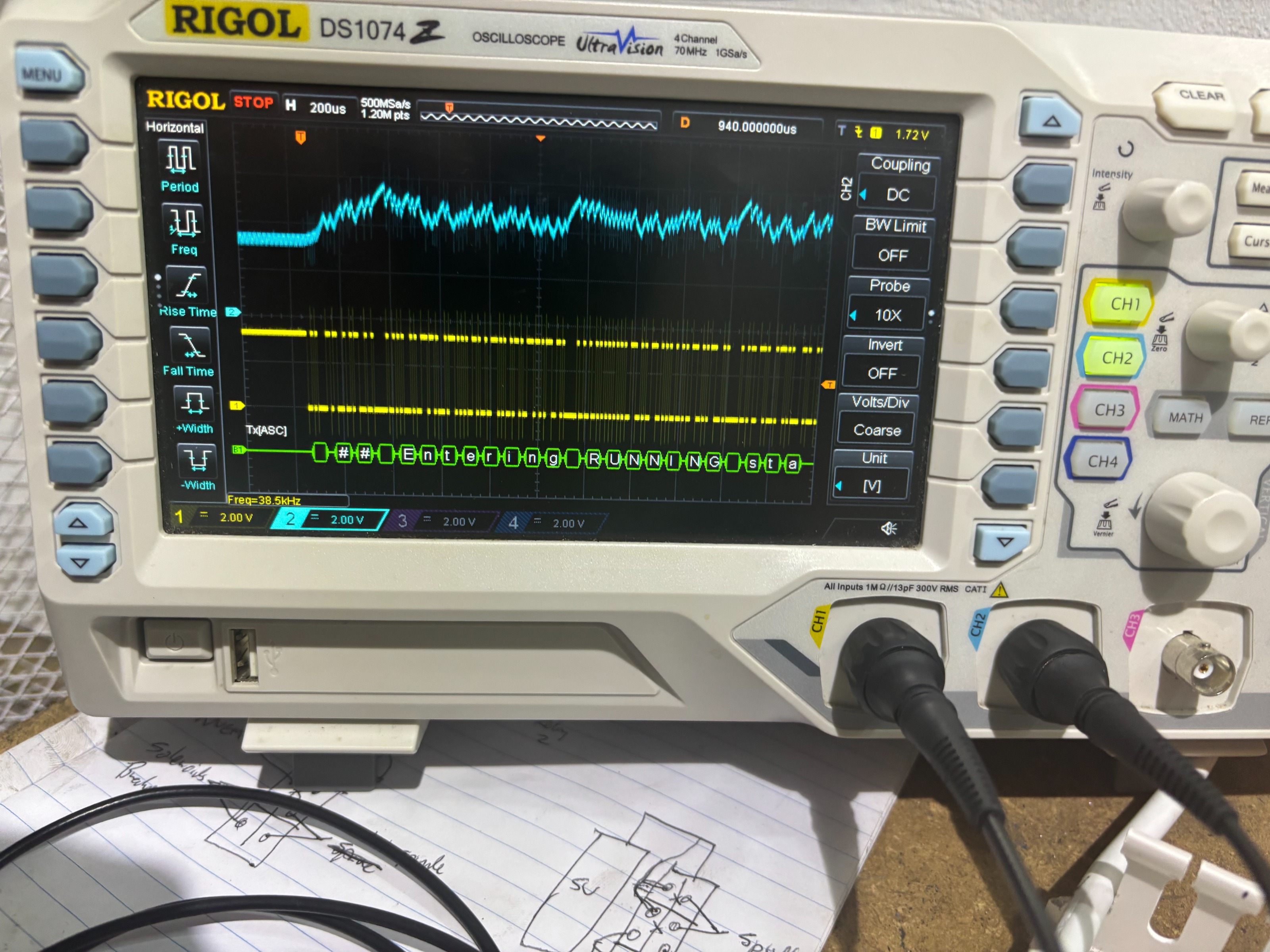
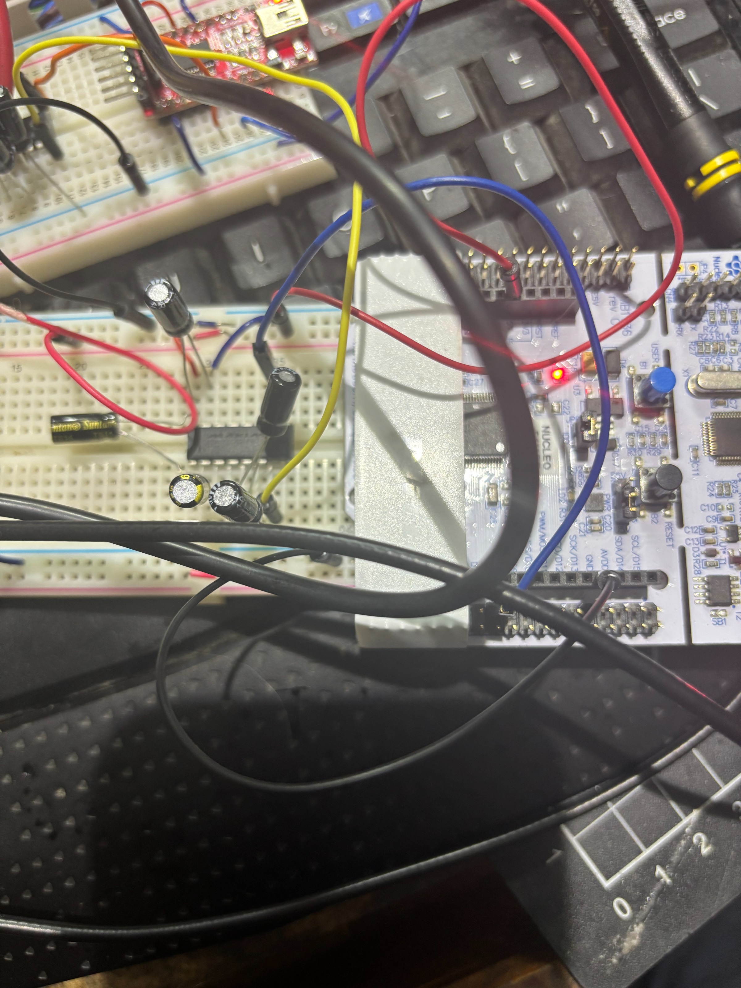
To compare, I built up my own circuit with a known working MAX232 chip with the charge capacitors as recommended in the data sheet. Probing my own chip allows me to measure the signal in and out at both TTL and RS232 levels cleanly on the scope so that tells me it's not my 10X probes loading the signal down. This was my initial theory looking at the long rise times. My own circuit was running at 5V so this could be the difference.
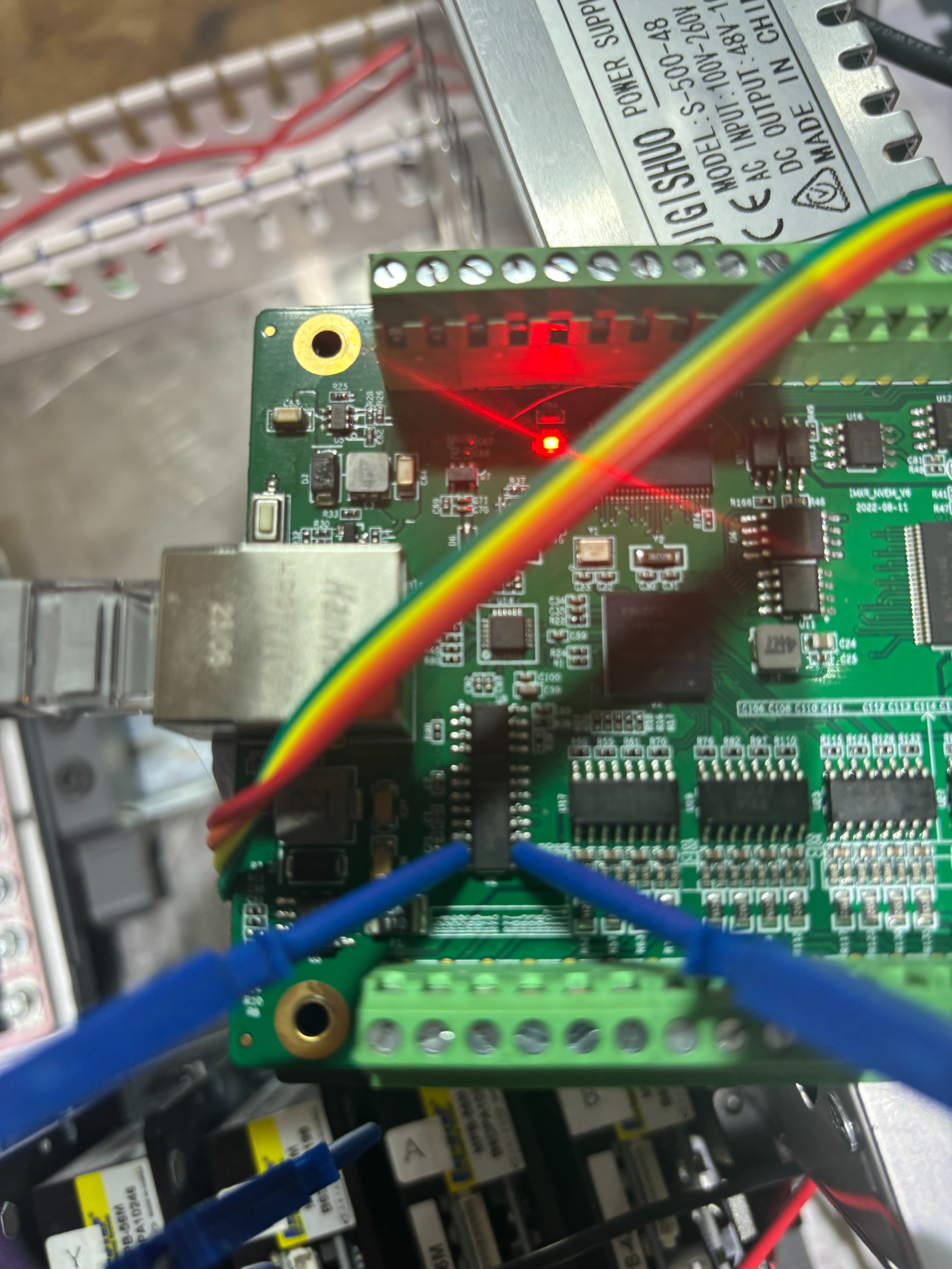
I'm not sure why signal coming out of the chip is so noisy. I can see on the board that the chip is getting 3V3 (Pin 16). The board seems to be missing one of the charge pump capacitors (C4 in the datasheet on V-, pin 6) and I wonder if this is the issue? The V+ and V- (pins 2 and 6) shows 4V across them which tells me it's doing something to multiply the voltage needed for RS232 transmission.
I could desolder the chip and see if it behaves properly with all of the recommended capacitors per the datasheet but at that point I'll probably just bypass it and run TTL out to an FTDI module. I see the NVEM manual says that the XH header has "undefined" behaviour so I was surprised to see the MAX232 chip there if they didn't intend to use it for a documented feature.
The PCB says it is a V6 dated 2022. Has anyone else experienced this issue? What do you typically see on the TX Line on the XH header?
I've probed the signal coming in TTL (Pin 10, yellow signal on oscilloscope) from the MCU, and also out from the MAX232 after conversion to RS232 (Pin 7, shown as the noisy signal in blue on the scope).
To compare, I built up my own circuit with a known working MAX232 chip with the charge capacitors as recommended in the data sheet. Probing my own chip allows me to measure the signal in and out at both TTL and RS232 levels cleanly on the scope so that tells me it's not my 10X probes loading the signal down. This was my initial theory looking at the long rise times. My own circuit was running at 5V so this could be the difference.
I'm not sure why signal coming out of the chip is so noisy. I can see on the board that the chip is getting 3V3 (Pin 16). The board seems to be missing one of the charge pump capacitors (C4 in the datasheet on V-, pin 6) and I wonder if this is the issue? The V+ and V- (pins 2 and 6) shows 4V across them which tells me it's doing something to multiply the voltage needed for RS232 transmission.
I could desolder the chip and see if it behaves properly with all of the recommended capacitors per the datasheet but at that point I'll probably just bypass it and run TTL out to an FTDI module. I see the NVEM manual says that the XH header has "undefined" behaviour so I was surprised to see the MAX232 chip there if they didn't intend to use it for a documented feature.
The PCB says it is a V6 dated 2022. Has anyone else experienced this issue? What do you typically see on the TX Line on the XH header?
Attachments:
Please Log in or Create an account to join the conversation.
- Huliofane
- Offline
- New Member
-
Less
More
- Posts: 2
- Thank you received: 0
10 Apr 2025 12:19 #326031
by Huliofane
Replied by Huliofane on topic Remora - ethernet NVEM / EC300 / EC500 cnc board
Sorry for disturb,i have an problem with my nvem board,is same as board on this topic,im write here but im undestand we are expert on pcb .....when im power on the grren led on lan port blink at 10% of light and speed,the item on pcbU7 "DE=G12" is hot and ,the led "D15" blink when insert a cable,the situation of led not change and switch or pc not blink he light.
we have any idea for solve my situation ??
sorry for disturb
we have any idea for solve my situation ??
sorry for disturb
Please Log in or Create an account to join the conversation.
Time to create page: 1.009 seconds