LinuxCNC-RIO - RealtimeIO for LinuxCNC based on FPGA (ICE40 / ECP5)

More
1 year 11 months ago #313869 by mBender
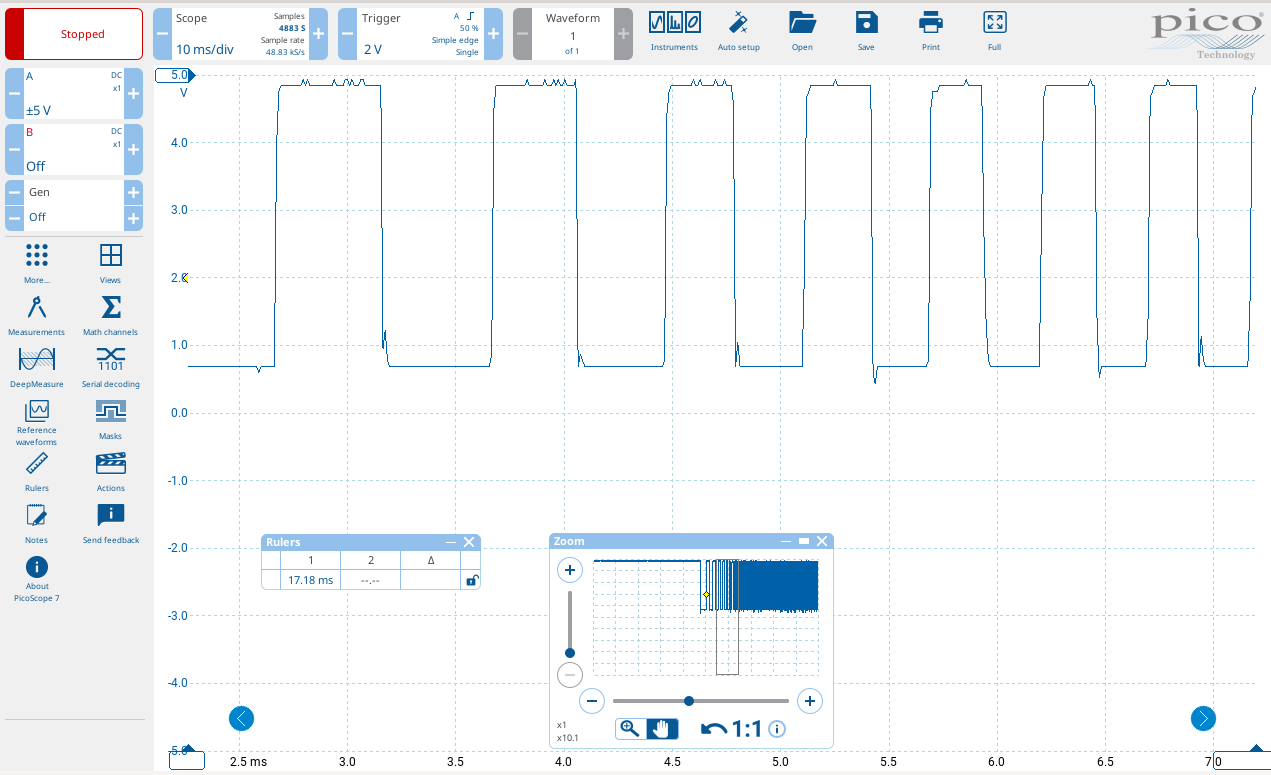
Heureka!! The new level shifter came in today and it works! I used the 3.3V to 12V and supplied 5V to the high voltage line. Even that works. On the Oscilloscope the Input side looks like a perfect square wave, the output side has a raising edge which is not super vertical. It looks like to doesn't make an issue. Will test the 3.3V to 5V lever shifter and see if that makes a difference.

What is the expected behavior of the direction signal. I was expecting that it's either permanently high or permanently low depending on the direction. It looks like that it's either permanent low and high only when a step impulse is created. Meaning it is kind of a square signal too. Is that correct?

Another question: I am running the tang 9k with ethernet. What happens if the ethernet connections drops during a move. Will the motors just stop?


Please Log in or Create an account to join the conversation.
More
1 year 11 months ago #313877 by meister

 Another question: I am running the tang 9k with ethernet. What happens if the ethernet connections drops during a move. Will the motors just stop?


yes, if the connection is broken, all systems goes into eStop, enable pins goes low and no steps will generated anymore


Please Log in or Create an account to join the conversation.

More
1 year 11 months ago #313912 by mBender
Awesome, I tested it this morning again. This is the signal of the output of the level shifter. Looks better as I had it in memory. I also confirmed, the Direction Signal is not a square signal. It's either on or off all the time depending on which direction the machine is traveling. It goes off, once the machine is not moving. I noticed there is sometimes a bit of delay until the direction signal goes off. I was able to see that when I looked at the LEDs of the level shifter.

I also noticed that the machine sounds smoother as when I run it with software stepping.

 
The following user(s) said Thank You: meister

Please Log in or Create an account to join the conversation.

More
1 year 11 months ago #313918 by digiex_chris


if i set the deadband to :
DEADBAND           = 0.0001

my DRO shows the exact position like 10.000 or 0.000

Thanks that helped! Also the flickering problem was actually the qtpyvcp UI I was using, not the actual internal machine position, so actually everything is working perfectly.

Here's the github repo for the board including production and assembly outputs for ordering a fully assembled board:
github.com/digiexchris/rio-solidwater-shield
The following user(s) said Thank You: meister

Please Log in or Create an account to join the conversation.

More
1 year 11 months ago #314028 by mBender
Below is the current set up as of last night. Bench testing worked as expected. It goes from there to a Parallel port break out board. This allwos me to use my machine with LinuxCNC and laserGRBL with just changing a plug. I tried to find out the current rating of the 3.3V and 5V power supply of the Tang Nano 9k. According to the schematics, it seems like that there is a TMI7003C DC/DC Step down, which gets it's 5V directly from the USB C port. If I read it correct, it can supply a max current of 1.5A total. That'a including the power for the FPGA,...It seems like the each Output of the Tang can drive up to 24mA. Which obviusley need to be deducted from the 1.5A plus the other current demands of the FPGA board. Still I believe there is plenty of current to drive secondary operations.The 1.8V needed for Bank 3 is not availbale at FPGA board. I was wondering if I could just use 1 or 2 1.8V outputs, set them pernantley to high and use them as supply voltage for any leverl shifter at Bank3. Opinions? 


Please Log in or Create an account to join the conversation.

More
1 year 11 months ago #314043 by digiex_chris

Below is the current set up as of last night. Bench testing worked as expected. It goes from there to a Parallel port break out board. This allwos me to use my machine with LinuxCNC and laserGRBL with just changing a plug. I tried to find out the current rating of the 3.3V and 5V power supply of the Tang Nano 9k. According to the schematics, it seems like that there is a TMI7003C DC/DC Step down, which gets it's 5V directly from the USB C port. If I read it correct, it can supply a max current of 1.5A total. That'a including the power for the FPGA,...It seems like the each Output of the Tang can drive up to 24mA. Which obviusley need to be deducted from the 1.5A plus the other current demands of the FPGA board. Still I believe there is plenty of current to drive secondary operations.The 1.8V needed for Bank 3 is not availbale at FPGA board. I was wondering if I could just use 1 or 2 1.8V outputs, set them pernantley to high and use them as supply voltage for any leverl shifter at Bank3. Opinions? 

 
My personal plan if I needed more gpio was to ignore the 1.8v pins and using the 3.3v pins either use a shift register, see if I could add i2c GPIO expansion support such as the mcp23017, or reserve the FPGA purely for estop, home pins, and steppers and use something else for things like MPG controls and such.  github.com/wezhunter/ESP32_LinuxCNC_MotionController_RealTime perhaps, since I have a pile of esp32S2's around. 
I also ended up with a XHC WHB04B-6 wireless MPG that currently satisfies 90% of my control needs, so I don't have a lot of willpower to make a UI that needs a lot of GPIO.

I know that doesn't solve your problem, but just thought I'd mention it for ideas. 

Also, a common LM317 is easy to make it output 1.8v from from the 5v input, as another option. 2 capacitors and 2 resistors. It's hard to even burn them out, they shut themselves down with overcurrent.


Please Log in or Create an account to join the conversation.

Time to create page: 0.272 seconds
Powered by Kunena Forum
