Rigid Tapping Help
- NCPatrol
- Offline
- Senior Member
-

Less
More
- Posts: 77
- Thank you received: 1
28 Jul 2018 17:20 #115020
by NCPatrol
Replied by NCPatrol on topic Rigid Tapping Help
This will probably turn in to a new thread in the right section....
So the encoder is working and technically tapping works, but I don't have enough torque without back gear. Apparently the previous owner/builder didn't get far with rigid tapping, or at least not anything big enough to need gears so the machine is not set up to tap (or really do anything cnc) in back gear.
Brainstorming a bit and reading some threads here, I'm thinking of a couple solutions
1) Could I put a micro switch on the back gear lever - when in gear and the switch is tripped, apply a reduction scale to the encoder and reverse the spindle (M4?)? I'm researching exactly what the 2J head reduction is, but it seems like it would be simple and would work. As a temporary solution, I could just do a manual switch to tell it that it's in gear.
2) Ditch the rotary encoder and do the gear encoder referenced on pico-system's site. From what I understand this can be challenging (but not impossible?) on a 2J due to the movement the gear makes to engage.
3) Go really hack and once I figure out the gear reduction in the head, apply that to the thread pitch in Fusion so Z moves properly relative to the reduced rotation speed. Not a long term solution but I could see it working in a pinch.
I feel like option 1 would be pretty easy to pull off. Any reason why I wouldn't want to go that direction?
Please Log in or Create an account to join the conversation.
- andypugh
-

- Offline
- Moderator
-

Less
More
- Posts: 19789
- Thank you received: 4605
28 Jul 2018 17:25 #115021
by andypugh
Replied by andypugh on topic Rigid Tapping Help
Where is the encoder mounted at the moment?
Please Log in or Create an account to join the conversation.
- NCPatrol
- Offline
- Senior Member
-

Less
More
- Posts: 77
- Thank you received: 1
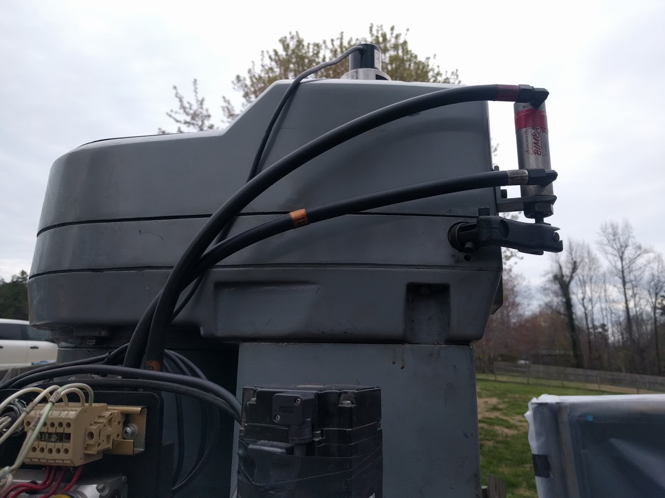
28 Jul 2018 17:27 - 28 Jul 2018 17:32 #115022
by NCPatrol
Replied by NCPatrol on topic Rigid Tapping Help
Last edit: 28 Jul 2018 17:32 by NCPatrol.
Please Log in or Create an account to join the conversation.
- andypugh
-

- Offline
- Moderator
-

Less
More
- Posts: 19789
- Thank you received: 4605
28 Jul 2018 17:37 #115023
by andypugh
Replied by andypugh on topic Rigid Tapping Help
I think it is worth checking that that doesn't still run at true spindle speed. (If you haven't already). With a drawbar setup that is where the drawbar would be, and those always have to spin at full spindle speed.
Please Log in or Create an account to join the conversation.
- NCPatrol
- Offline
- Senior Member
-

Less
More
- Posts: 77
- Thank you received: 1
28 Jul 2018 22:13 #115030
by NCPatrol
Replied by NCPatrol on topic Rigid Tapping Help
No, it definitely does not match spindle speed when it's in back gear.
I'd have to dig up the assembly diagram to remember the exact configuration, but I know it's basically 1:1 direct when it's out of back gear. When you engage the gears, it disconnects the direct drive and runs it through the gear train.
As a quick example, I had a threaded program that ran a 400rpm out of back gear. In gear, it still showed 400 but the spindle was obviously spinning much, much slower.
Please Log in or Create an account to join the conversation.
- andypugh
-

- Offline
- Moderator
-

Less
More
- Posts: 19789
- Thank you received: 4605
28 Jul 2018 22:40 #115031
by andypugh
What is "it" in this example?
It seems to me that the drawbar (on heads fitted with a drawbar) always spins at spindle speed, and if the encoder was connected to a drawbar-surrogate (which would be the easiest way to do it) then the encoder would always read true spindle position.
Dividing-down the encoder isn't usually an option as the index won't then happen once-per-rev.
Replied by andypugh on topic Rigid Tapping Help
In gear, it still showed 400 but the spindle was obviously spinning much, much slower.
What is "it" in this example?
It seems to me that the drawbar (on heads fitted with a drawbar) always spins at spindle speed, and if the encoder was connected to a drawbar-surrogate (which would be the easiest way to do it) then the encoder would always read true spindle position.
Dividing-down the encoder isn't usually an option as the index won't then happen once-per-rev.
Please Log in or Create an account to join the conversation.
- NCPatrol
- Offline
- Senior Member
-

Less
More
- Posts: 77
- Thank you received: 1
28 Jul 2018 22:57 - 28 Jul 2018 23:01 #115033
by NCPatrol
Replied by NCPatrol on topic Rigid Tapping Help
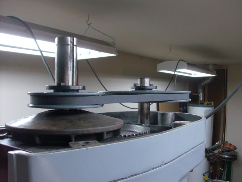
This is Serries 2 Boss 5...I don't know that any of the Boss series came with a drawbar, though there is some conflicting information out there on this topic.
This head is very different from a standard Bridgeport head in that it was 100% designed for CNC out of the box - ball screws, no quill, etc. I believe the back gear setup is entirely different too.
This is the only pic I can find of my head at the moment. The encoder is on the shaft closest to you, left side of the picture. That shaft's speed remains constant relative to the motor. The gear train is directly below that.
Last edit: 28 Jul 2018 23:01 by NCPatrol.
Please Log in or Create an account to join the conversation.
- andypugh
-

- Offline
- Moderator
-

Less
More
- Posts: 19789
- Thank you received: 4605
28 Jul 2018 23:02 #115034
by andypugh
Replied by andypugh on topic Rigid Tapping Help
You didn't answer the "it" question.
If "it" is the commanded spindle speed then you would expect a disparity.
But have you monitored the spindle encoder velocity pin? Note that it measures in revs per _second_.
If "it" is the commanded spindle speed then you would expect a disparity.
But have you monitored the spindle encoder velocity pin? Note that it measures in revs per _second_.
Please Log in or Create an account to join the conversation.
- andypugh
-

- Offline
- Moderator
-

Less
More
- Posts: 19789
- Thank you received: 4605
28 Jul 2018 23:04 #115036
by andypugh
Replied by andypugh on topic Rigid Tapping Help
Is the shaft hollow? Is there a true-speed shaft available down the bore?
Please Log in or Create an account to join the conversation.
- NCPatrol
- Offline
- Senior Member
-

Less
More
- Posts: 77
- Thank you received: 1
29 Jul 2018 01:04 #115039
by NCPatrol
"It" was referencing to the rpm shown on the linuxcnc display. Simple tapping program with spindle speed of 400. Out of back gear, displays shows ~400 and actual spindle speed (assumed) matches. In back gear, display still shows 400 but spindle speed is much slower. (Still looking for exact back gear ratio.)
The spindle is not hollow. Don't believe there's a way to get true speed in that shaft when in back gear.
Replied by NCPatrol on topic Rigid Tapping Help
You didn't answer the "it" question.
If "it" is the commanded spindle speed then you would expect a disparity.
But have you monitored the spindle encoder velocity pin? Note that it measures in revs per _second_.
"It" was referencing to the rpm shown on the linuxcnc display. Simple tapping program with spindle speed of 400. Out of back gear, displays shows ~400 and actual spindle speed (assumed) matches. In back gear, display still shows 400 but spindle speed is much slower. (Still looking for exact back gear ratio.)
The spindle is not hollow. Don't believe there's a way to get true speed in that shaft when in back gear.
Please Log in or Create an account to join the conversation.
Time to create page: 0.112 seconds


