[ Vfdmod ] An easy VFD control over MODBUS RTU
- Zbysob1
- Offline
- New Member
-

Less
More
- Posts: 17
- Thank you received: 0
20 Mar 2021 07:26 #202936
by Zbysob1
Replied by Zbysob1 on topic [ Vfdmod ] An easy VFD control over MODBUS RTU
Well then ... ") I have another Altivar 28 inverter and in it I have to send a signal to restore factory values to the register and after a while set its value to 0x8000 Hex to skip modbus checking. If I do not do this, after a few seconds of operation, the inverter shows a bus error and stops work. How do I add the function of sending the value 0x8000 to the register to the RESET button of Vfdmod. FaultResetCoil = 0x0190 and the reset value is 0x0001. After the reset, the register is automatically reset and I have to send 0x8000 to it
I have another Altivar 28 inverter and in it I have to send a signal to restore factory values to the register and after a while set its value to 0x8000 Hex to skip modbus checking. If I do not do this, after a few seconds of operation, the inverter shows a bus error and stops work. How do I add the function of sending the value 0x8000 to the register to the RESET button of Vfdmod. FaultResetCoil = 0x0190 and the reset value is 0x0001. After the reset, the register is automatically reset and I have to send 0x8000 to it
By the way, how to send modbus commands to the inverter from linux. I mean some simple program so that I can reset the inverter with Linuxcnc running from the terminal or some program. Now I have to start Windows and use modbusMAT to send reset and set modbus communication control to 0x8000.
I have another Altivar 28 inverter and in it I have to send a signal to restore factory values to the register and after a while set its value to 0x8000 Hex to skip modbus checking. If I do not do this, after a few seconds of operation, the inverter shows a bus error and stops work. How do I add the function of sending the value 0x8000 to the register to the RESET button of Vfdmod. FaultResetCoil = 0x0190 and the reset value is 0x0001. After the reset, the register is automatically reset and I have to send 0x8000 to itBy the way, how to send modbus commands to the inverter from linux. I mean some simple program so that I can reset the inverter with Linuxcnc running from the terminal or some program. Now I have to start Windows and use modbusMAT to send reset and set modbus communication control to 0x8000.
Please Log in or Create an account to join the conversation.
- aekhv
-
 Topic Author
- Offline
- Senior Member
-

Less
More
- Posts: 49
- Thank you received: 18
21 Mar 2021 10:51 - 21 Mar 2021 10:53 #203103
by aekhv
Replied by aekhv on topic [ Vfdmod ] An easy VFD control over MODBUS RTU
At this moment the only way to realize your wish is to modify vfdmod sources, or try to deep into MB2HAL.How do I add the function of sending the value 0x8000 to the register to the RESET button of Vfdmod. FaultResetCoil = 0x0190 and the reset value is 0x0001. After the reset, the register is automatically reset and I have to send 0x8000 to it
Last edit: 21 Mar 2021 10:53 by aekhv.
Please Log in or Create an account to join the conversation.
- Zbysob1
- Offline
- New Member
-
Less
More
- Posts: 17
- Thank you received: 0
25 Mar 2021 06:43 #203587
by Zbysob1
Replied by Zbysob1 on topic [ Vfdmod ] An easy VFD control over MODBUS RTU
Ok, I managed somehow with modpoll. If I send a command to the inverter to restore the factory settings, there are modbus communication errors, but the LED is generally green and I can control the motor. How does the FAULT RESET button work?
Because that's where I enter the registry address to restore the factory settings and the value 1, i.e. restore. Then this register is automatically set to 0. The question is whether the use of the button will send this value to this register and how many times does it do it because other values are sent constantly - this is how it results from viewing the modbus communication
Because that's where I enter the registry address to restore the factory settings and the value 1, i.e. restore. Then this register is automatically set to 0. The question is whether the use of the button will send this value to this register and how many times does it do it because other values are sent constantly - this is how it results from viewing the modbus communication
Please Log in or Create an account to join the conversation.
- pinsyd1
- Offline
- New Member
-
Less
More
- Posts: 3
- Thank you received: 1
12 Aug 2021 13:18 #217610
by pinsyd1
Replied by pinsyd1 on topic [ Vfdmod ] An easy VFD control over MODBUS RTU
Hi, this is outstanding, very easy to learn and use. But.... I'm not there yet.
I've been trying for three days to get this to play nice with a Bosch Rexroth EFC 3610 VFD. As best as I can tell the "words" (0x03 and 0x10) are not actually handled properly (or Bosch Rexroth is non-compliant) as there is no way to define how many words and number of Byte.
Things that work:
1. vfdmod.rs485.Is-connected = True
2. SpindleRpmOut = Value on front of VFD display (excluding multiplier)
So I'm confident the comms is working but the "writes" are not working. Now, my VFD doesn't work on RPM but xxx / 400hz out of 24,400 RPM. So if the VFD is set to 188 / 400 = 24k * (188 / 400) = 11,280 RPM. Maybe I've misconfigured it, happy to show RPM on display instead of xxx / 400hz if that makes the problem go away.
According to the Modbus commuications example to set the frequency section "14.3.5 Modbus Communication Example
- Example 1" and "Tab. 14-18 - Function 0x10: Write N register words, range: 1...16" of the manual
- Expected Frequency forward rotation (0X0081) at frequency of 50.00Hz (represented by 5,000 = 0X1388) internally
[01][10][7F][00][02][04][00][81][13][88][8A][E3]
- Value sent by vfdmod at frequency of 20.00Hz (0x0088)
[01][10][7F][00][00][01][02][00][88][28][F1]
ini
I've been trying for three days to get this to play nice with a Bosch Rexroth EFC 3610 VFD. As best as I can tell the "words" (0x03 and 0x10) are not actually handled properly (or Bosch Rexroth is non-compliant) as there is no way to define how many words and number of Byte.
Things that work:
1. vfdmod.rs485.Is-connected = True
2. SpindleRpmOut = Value on front of VFD display (excluding multiplier)
So I'm confident the comms is working but the "writes" are not working. Now, my VFD doesn't work on RPM but xxx / 400hz out of 24,400 RPM. So if the VFD is set to 188 / 400 = 24k * (188 / 400) = 11,280 RPM. Maybe I've misconfigured it, happy to show RPM on display instead of xxx / 400hz if that makes the problem go away.
According to the Modbus commuications example to set the frequency section "14.3.5 Modbus Communication Example
- Example 1" and "Tab. 14-18 - Function 0x10: Write N register words, range: 1...16" of the manual
- Expected Frequency forward rotation (0X0081) at frequency of 50.00Hz (represented by 5,000 = 0X1388) internally
[01][10][7F][00][02][04][00][81][13][88][8A][E3]
- Value sent by vfdmod at frequency of 20.00Hz (0x0088)
[01][10][7F][00][00][01][02][00][88][28][F1]
Opening /dev/ttyUSB0 at 9600 bauds (N, 8, 1)

vfdmod: reading 'spindle.rpm-out' from address 4096 (0x1000)...
[01][03][10][00][00][01][80][CA]
Waiting for a confirmation...
<01><03><02><49><70><8E><30>
vfdmod: returned value is 18800 (0x4970)

vfdmod: setting command speed value to 20 (0x0014)...
[01][10][7F][00][00][01][02][00][14][28][98]
Waiting for a confirmation...
<01><10><7F><00><00><01><18><1D>

vfdmod: setting control word value to 136 (0x0088)...
[01][10][7F][00][00][01][02][00][88][28][F1]
Waiting for a confirmation...
<01><10><7F><00><00><01><18><1D>
ini
# **********************************************************
#
# Predefined (required) groups start here! These groups are:
#
# [Common]
# [RS485]
# [Control]
# [SpindleRpmIn]
# [SpindleRpmOut]
#
# **********************************************************

[Common]

# HAL component name. Default value is 'vfdmod'.
;ComponentName=vfdmod

# A maximum spindle speed shall be greater than zero.
MaxSpeedRPM=24000

# A minimum spindle speed shall be greater than zero
# and lower than (or equal to) MaxSpeedRPM.
MinSpeedRPM=2

# A maximum allowed difference between command speed and output speed
# to set HAL 'at-speed' output to TRUE.
# 0.00 = 0%
# 1.00 = 100%
# Default value is 0.05 (5%).
AtSpeedThreshold=0.25

[RS485]

# VFD slave address.
SlaveAddress=1

# Serial device system path.
SerialDevice=/dev/ttyUSB0

# Communication speed.
BaudRate=9600

# Data bits: always 8.
;DataBits=8

# Parity: 'N' for none (default), 'E' for even, 'O' for odd.
;Parity=N

# Stop bits: 1 (default) or 2.
;StopBits=1

# Loop delay in milliseconds, default value is 200 ms.
# Range: 0 ... 10000.
LoopDelay=10000

# Delay in characters at front of every MODBUS request.
# MODBUS specification recommends at least 3.5 characters,
# so default value must be 4.
# Increase this value if communication errors happen.
# Range: 0 ... 100.
ProtocolDelay=94

# A minimum count of successfull requests to set HAL 'is-connected' output
# to TRUE. Default value is 10. Range: 1 ... 100.
;IsConnectedDelay=10

# Comma separated critical errors that call reconnection event.
# For example: error code 5 occures when SerialDevice has been
# physically disconnected.
;ConnectionErrorList=5

# Delay in milliseconds between reconnection attempts, this parameter
# is active when ConnectionErrorList is not empty. Default value is 1000 ms.
# Range: 0 ... 10000.
;ConnectionDelay=1000

[Control]

# Function code:
# 0x06 - write single register (default).
# 0x10 - write multiple registers.
# 0x05 - write single coil.
# 0x0F - write multiple coils.
;FunctionCode=0x06
FunctionCode=0x10

# **********************************************************
# Values below are active when FunctionCode is 0x06 or 0x10.
# **********************************************************

# An address of the control register.
Address=0x7F00

# A value to run spindle forward.
RunForwardValue=0x0081

# A value to run spindle reverse.
RunReverseValue=0x0085

# A value to reset a fault state.
# If this parameter is commented then fault reset feature will be disabled.
;FaultResetValue=0x04A8

# A value to stop spindle.
StopValue=0x0088


[SpindleRpmIn]

# Function code:
# 0x06 - write single register (default).
# 0x10 - write multiple registers.
;FunctionCode=0x06
FunctionCode=0x10

# An address of the command speed (or frequency) register.
Address=0x7F00

# Multiplier and Divider are integer values to correct command speed value
# before it will be written to command speed register.
# Corrected command speed = (command speed) x Multiplier / Divider.
# Use both (Multiplier & Divider) to reach float coefficient.
Multiplier=10
;Divider=1

[SpindleRpmOut]
FunctionCode=0x03

# An address of the output speed (or frequency) register.
Address=0x1000

# Multiplier and Divider are integer values to correct output speed value
# after it has been read from output speed register.
# Corrected output speed = (output speed) x Multiplier / Divider.
# Use both (Multiplier & Divider) to reach float coefficient.
Multiplier=100
;Divider=1Please Log in or Create an account to join the conversation.
- Roguish
-

- Offline
- Elite Member
-

Less
More
- Posts: 297
- Thank you received: 31
24 Aug 2021 17:16 - 24 Aug 2021 17:16 #218628
by Roguish
Replied by Roguish on topic [ Vfdmod ] An easy VFD control over MODBUS RTU
Hello.
interesting vfd controller comp.
does anyone have this working with a Delta VFD-E ???
could you share your .hal files, please?
thanks.
interesting vfd controller comp.
does anyone have this working with a Delta VFD-E ???
could you share your .hal files, please?
thanks.
Last edit: 24 Aug 2021 17:16 by Roguish. Reason: correct spelling.....
Please Log in or Create an account to join the conversation.
- iforce2d
- Offline
- Senior Member
-
Less
More
- Posts: 44
- Thank you received: 17
24 Aug 2021 19:02 #218634
by iforce2d
Replied by iforce2d on topic [ Vfdmod ] An easy VFD control over MODBUS RTU
Thanks for making this mod, I find it more approachable than the mb2hal so far.
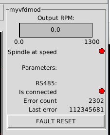
I'm using the same inverter as Zbysob1, the YL620. I set up the .ini myself by following the docs for vfdmod and the manual for the inverter, and came to pretty much the same settings as Zbysob1 used. According to the debug output the VFD is responding, but with invalid values. The LED display never turns green and the error is shown as 112345681.
I don't think this is caused by wiring noise because the returned values are always the same, and when viewed with an oscilloscope the noise does not look bad enough to be causing a problem.
Here's my .ini file www.iforce2d.net/tmp/linuxcnc/vfdmod_YL620.ini
VFD settings are as factory reset except for changing baud rate to 9600 and slave address to 1, and of course control method to use RS485.
How can we tell what the meaning of the error code 112345681 is?
If Zbysob1 is still here, I wonder if you could share the final config file you ended up with?
I'm using the same inverter as Zbysob1, the YL620. I set up the .ini myself by following the docs for vfdmod and the manual for the inverter, and came to pretty much the same settings as Zbysob1 used. According to the debug output the VFD is responding, but with invalid values. The LED display never turns green and the error is shown as 112345681.
vfdmod: reading 'spindle.rpm-out' from address 8203 (0x200B)...
[01][03][20][0B][00][01][FE][08]
Waiting for a confirmation...
<01><83><03><01><31>
ERROR Illegal data value

vfdmod: setting command speed value to 5 (0x0005)...
[01][06][20][01][00][05][13][C9]
Waiting for a confirmation...
<01><86><03><02><61>
ERROR Illegal data value
I don't think this is caused by wiring noise because the returned values are always the same, and when viewed with an oscilloscope the noise does not look bad enough to be causing a problem.
Here's my .ini file www.iforce2d.net/tmp/linuxcnc/vfdmod_YL620.ini
VFD settings are as factory reset except for changing baud rate to 9600 and slave address to 1, and of course control method to use RS485.
How can we tell what the meaning of the error code 112345681 is?
If Zbysob1 is still here, I wonder if you could share the final config file you ended up with?
Please Log in or Create an account to join the conversation.
- Aciera
-

- Offline
- Administrator
-

Less
More
- Posts: 4706
- Thank you received: 2106
24 Aug 2021 19:31 #218636
by Aciera
Replied by Aciera on topic [ Vfdmod ] An easy VFD control over MODBUS RTU
The VFD is sending you an error code 3 (3rd number in the response)
Which, according to the manual means:
3 = The bit and word values indicated in the request are not accessible in the slave.
So it looks like you've got the registers for the requested values in the VFD wrong.
Which, according to the manual means:
3 = The bit and word values indicated in the request are not accessible in the slave.
So it looks like you've got the registers for the requested values in the VFD wrong.
Please Log in or Create an account to join the conversation.
- iforce2d
- Offline
- Senior Member
-
Less
More
- Posts: 44
- Thank you received: 17
25 Aug 2021 02:46 #218667
by iforce2d
Replied by iforce2d on topic [ Vfdmod ] An easy VFD control over MODBUS RTU
Thanks Aciera. I used a utility called
mbpoll
and this bash script to attempt reads from every register, and I always get the same replyExample run:So I guess my problem is not actually related to vfdmod. The VFD is simply rejecting all attempts to even read any register whatsoever.
fwiw I read the VFD manual from cover to cover three times searching for any mention of modbus/RS485 and changed all related parameters as necessary, like this (for YL620):
P00,01 Start/stop command source -> 3: Motor controlled by Modbus RS485
P03.00 RS485 baud rate -> 3: 9600bps
P03.01 RS485 address -> 1
P03.02 RS485 format -> 2: 8N1
P07.08 1st frequency selection source -> 5: Modbus RS485 given frequency
Setting the first one prevents me from using the onboard panel to start/stop the motor, so I can tell it is having some effect. The P03 ones are also taking effect because if I don't match them with parameters used by the master then the connection doesn't work at all. The last one (P07.08) I can't really check until the other problems are solved, but I set it to RS485 anyway. I wonder if there is some setting needed that is not mentioned in the manual - that would not surprise me since it's a pretty crap manual, and I've seen other people say that their manual didn't even mention the P00.01 option of 3 as above.
Anyway I've been struggling with this for 16 hours straight now and questioning if it's even worth it, need some sleep...
#!/bin/bash
for i in {0..65535}
do
   mbpoll -b 9600 -1 -P none -r $i -t 4 -v /dev/ttyUSB0
donechris@cnc:~$ ./test.sh &> out.txt
chris@cnc:~$ grep "failed" out.txt | wc -l
65535fwiw I read the VFD manual from cover to cover three times searching for any mention of modbus/RS485 and changed all related parameters as necessary, like this (for YL620):
P00,01 Start/stop command source -> 3: Motor controlled by Modbus RS485
P03.00 RS485 baud rate -> 3: 9600bps
P03.01 RS485 address -> 1
P03.02 RS485 format -> 2: 8N1
P07.08 1st frequency selection source -> 5: Modbus RS485 given frequency
Setting the first one prevents me from using the onboard panel to start/stop the motor, so I can tell it is having some effect. The P03 ones are also taking effect because if I don't match them with parameters used by the master then the connection doesn't work at all. The last one (P07.08) I can't really check until the other problems are solved, but I set it to RS485 anyway. I wonder if there is some setting needed that is not mentioned in the manual - that would not surprise me since it's a pretty crap manual, and I've seen other people say that their manual didn't even mention the P00.01 option of 3 as above.
Anyway I've been struggling with this for 16 hours straight now and questioning if it's even worth it, need some sleep...
Please Log in or Create an account to join the conversation.
- iforce2d
- Offline
- Senior Member
-
Less
More
- Posts: 44
- Thank you received: 17
25 Aug 2021 16:32 #218718
by iforce2d
Replied by iforce2d on topic [ Vfdmod ] An easy VFD control over MODBUS RTU
Just an update on my YL620 woes. I eventually gave up trying to use the RS485 port that would normally be used for external PC control. It simply does not accept any messages at all, and always gives "Illegal data value" no matter what.
I noticed in the manual that the built in LCD panel is also communicating via RS485, at 19200 baud and fixed address of 10. I disconnected it and used a logic analyzer to view the signals it was sending. Turns out the manual was wrong, this link runs at 38400 baud! At least the address was correct, and the signal looks like normal modbus.
Then I connected my USB/RS485 adapter to the plug that the LCD panel had been using, and did a factory reset so that control would be returned to that port. And that.... just worked with no problems.
At least, the connection is ok. No errors and the LED display is green, and in the debug output I can see values are being set in the VFD registers without any faults. Now my next problem is that vfdmod never sends the "RunForward" value to command the spindle to start. Here is my setting for that register:And here is what it sends, no matter what I do in the LinuxCNC GUI:I can see the other register (command speed) being changed when I click the + button in the GUI to increase the speed. But of course the spindle will not start if it's continuously being sent the StopValue (0x0001) command. I'm new to LinuxCNC so perhaps I'm missing something, but I thought the spindle should start if I disable e-stop (red cross button), then enable motors (orange power button), then click either forward or reverse for motor direction, and then increase the speed.... right?
YouTube video:
I noticed in the manual that the built in LCD panel is also communicating via RS485, at 19200 baud and fixed address of 10. I disconnected it and used a logic analyzer to view the signals it was sending. Turns out the manual was wrong, this link runs at 38400 baud! At least the address was correct, and the signal looks like normal modbus.
Then I connected my USB/RS485 adapter to the plug that the LCD panel had been using, and did a factory reset so that control would be returned to that port. And that.... just worked with no problems.
At least, the connection is ok. No errors and the LED display is green, and in the debug output I can see values are being set in the VFD registers without any faults. Now my next problem is that vfdmod never sends the "RunForward" value to command the spindle to start. Here is my setting for that register:
[Control]

Address=0x2000
RunForwardValue=0x0012
RunReverseValue=0x0022
FaultResetValue=0x0080
StopValue=0x0001vfdmod: setting control word value to 1 (0x0001)...
[0A][06][20][00][00][01][42][B1]
Waiting for a confirmation...
<0A><06><20><00><00><01><42><B1>YouTube video:
Please Log in or Create an account to join the conversation.
- Aciera
-
- Offline
- Administrator
-
Less
More
- Posts: 4706
- Thank you received: 2106
25 Aug 2021 17:51 - 25 Aug 2021 18:26 #218724
by Aciera
Replied by Aciera on topic [ Vfdmod ] An easy VFD control over MODBUS RTU
Have you made the necessary connections in your hal?
net spindle-cmd-rpm => vfdmod.spindle.rpm-in
net spindle-at-speed <= vfdmod.spindle.at-speed
net spindle-cw spindle.0.forward => vfdmod.control.run-forward
net spindle-ccw spindle.0.reverse => vfdmod.control.run-reverse
[edit]
And if you have, can you see the spindle-cw signal go true in the Hal show tool?
Last edit: 25 Aug 2021 18:26 by Aciera.
Please Log in or Create an account to join the conversation.
Time to create page: 0.131 seconds