Current turning capabilities status
- andypugh
-

- Offline
- Moderator
-

- Posts: 19863
- Thank you received: 4636
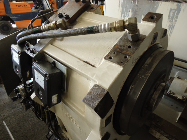
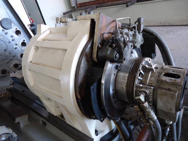
I would LOVE to use the current spindle motor as it is built in the spindle. This is very good as no belts are present. The reason is that the spindle motor drive is damaged, being this one of the reasons to start the conversion. Even if it was not damaged the protocol to the main drive is for sure "closed".
I searched a lot and I could not found any possibility off using the current motor spindle as it seams it is proprietary from Okuma.
There are only a few possible designs of motor, and there are ways to drive all of them with LinuxCNC.
Do you know what type of motor it is? Any pictures? What connectors are there?
Please Log in or Create an account to join the conversation.
- emcPT
-
 Topic Author
- Offline
- Platinum Member
-

- Posts: 424
- Thank you received: 95
Now, the issue is that the motor plate informs:
170V 98A
I believe that the 98A are at full 15Kw peak power, that the motor plate also informs.
I think that VFD drives are build to work at 400VAC or 220VAC, so I have no idea how to obtain the 170VAC needed.
Please Log in or Create an account to join the conversation.
- andypugh
-
- Offline
- Moderator
-
- Posts: 19863
- Thank you received: 4636
That tells us that it is three-phase.The motor is AC for sure. There are 3 thick wires marked as U V W.
It could still be a 3-phase permanent-magnet motor (variously called PMAC, BLDC, AC Servo, Synchronous AC) or it could indeed be a simple 3-phase induction motor.
Are there any other wires from the motor to the drive?
There are drives that can control almost any motor type, the CT Unidrive, for example:
www.ebay.co.uk/itm/200883844151
But as you can see, they are not at all cheap.
I _think_ that most motors are OK at higher than nameplate voltage as long as the current is suitably limited by the drive.Now, the issue is that the motor plate informs:
170V 98A
I believe that the 98A are at full 15Kw peak power, that the motor plate also informs.
I think that VFD drives are build to work at 400VAC or 220VAC, so I have no idea how to obtain the 170VAC needed.
Please Log in or Create an account to join the conversation.
- cmorley
- Offline
- Moderator
-
- Posts: 7316
- Thank you received: 2147
Please Log in or Create an account to join the conversation.
- emcPT
-
Topic Author
- Offline
- Platinum Member
-
- Posts: 424
- Thank you received: 95
I have no idea and I also do not know how can I figure it out. Never less I think I cannot buy such a servo drive (almost 100A) to test it. I simply have no means to do such an insane thing (€ $)
My simple approach was to take out the motor and do not use the C axis. But of course using the main already mounted motor would make the machine much better.
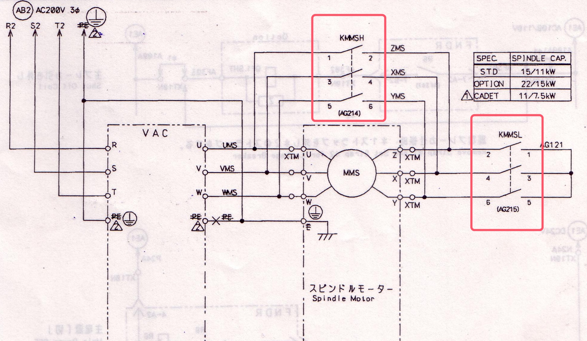
From the electrical schematic there are 6 wires that are leaving the motor. The wires are for connecting the Y or delta, to achieve two range speeds (commuted by either KMMSH and KMMSL (high and low)), for this reason I think it is a "standard induction motor", as those 6 wires can be compared as the connection box of a standard induction motor but my knowledge on this matter is low. I have attached a picture from the schematic. Previous, when I was trying to use all the hardware I posted in CNCzone, but I had no clear reply about what motor is it or if I could control it. Most reply's were negative.
Thank you
Please Log in or Create an account to join the conversation.
- emcPT
-
Topic Author
- Offline
- Platinum Member
-
- Posts: 424
- Thank you received: 95
At 5000rpm almost no vibration, it is quite amazing. It is also oil cooled for tight dimension work.
Please Log in or Create an account to join the conversation.
- andypugh
-
- Offline
- Moderator
-
- Posts: 19863
- Thank you received: 4636
From the electrical schematic there are 6 wires that are leaving the motor. The wires are for connecting the Y or delta, to achieve two range speeds (commuted by either KMMSH and KMMSL (high and low)), for this reason I think it is a "standard induction motor",
That does seem likely, looking at the diagram.
One way to tell might be to connect a low current supply to two of the wires (say 1A between U and V) and see if you can feel any "notches" as you rotate the motor.
I don't think you will feel any with an induction motor, whereas you will with a permanent magnet motor.
Does the rest of the wiring diagram show any more wires from the motor/spindle to the drive? If the only other wires from the spindle are an incremental encoder then I think it probably is just an induction motor.
This does mean that just about any VFD will work.
I am wondering if it might be worth trying to fix:
www.ebay.co.uk/itm/271142818043
I have no idea how important the missing parts are.
Please Log in or Create an account to join the conversation.
- andypugh
-
- Offline
- Moderator
-
- Posts: 19863
- Thank you received: 4636
I am wondering if it might be worth trying to fix:
www.ebay.co.uk/itm/271142818043.
Forget that, I miss-read the power.
For your spindle you would need:
www.motorcontrolwarehouse.co.uk/unidrive-sp2403/prod_328.html
The reason I suggest these drives is that they can control an induction motor in closed-loop using an encoder. This ought to give you a working C axis.
For rather less money, but rather more of a gamble, there is:
www.ebay.co.uk/itm/111005078898
Please Log in or Create an account to join the conversation.
- Kirk_Wallace
- Offline
- Junior Member
-

- Posts: 25
- Thank you received: 1
I'd sure like to see the rest of the dashed (actually ghost lined) box labeled spindle motor to see what else is considered part of the motor.
There are not that many ways to tell a VFD what you want, +/- 5 or 10 Volts, PWM/Direction, Modbus, maybe one or two more, but LinuxCNC covers them all so far. Finding the rest of the VAC box in the schematic might help. Also, looking at all of the connectors going to the VFD -- the number and size of the pins on a connector can indicate its function. Getting the make and model number on the VFD can lead to a manual down load from the manufacturer's website. One just needs to be in Sherlock mode.
I've been working on part of the user interface for a new lathe manufacturer. This may be released sometime in the nearish future. It may be an example configuration that can move the state of the LinuxCNC lathe art forward a little.
--
Kirk
www.wallacecompany.com/machine_shop/
Please Log in or Create an account to join the conversation.
- PCW
-

- Offline
- Moderator
-
- Posts: 17927
- Thank you received: 5251
To determine whether it is a PMSM servo motor or induction motor, you can also short out one winding (probably you would have to short U to X? if the relays are disconnected, in any case use an ohmmeter to find a winding to short) and turn the spindle. It will have a lot of resistance to turning if a winding is shorted and its a servo motor, but shorting will not make any difference if its an induction motor.
Please Log in or Create an account to join the conversation.