Considering a Full Rewire on a Working Schaublin 125 CNC

More
6 months 3 weeks ago #345339 by Dudelbert
"On second thought, in this kind of project I might use nested PID" that sounds super fancy, but I see two problems with it for me. For one, I would not know where even to start implementing this. And second, the motor RPM that I get is way too inaccurate for PID to effectively work.

I get the value from a 4–20 mA current from the VFD. I then have a 470 ohm resistor very close to my 7i84 that has the ADC to give me the signal I then process to get an RPM. The signal is rock solid, with no noticeable jitter at all, but it is only an 8-bit ADC, and my voltage is between 1.7 V and a little over 9 V, using less than half of the ADC range.

For getting an approximate gear ratio, this seems fine, but not for actual speed control, at least that is what I think. I may very well be wrong.
The following user(s) said Thank You: NWE

Please Log in or Create an account to join the conversation.

More
6 months 3 weeks ago #345340 by RotarySMP
By the way, this is the HAL and COMP I have gotten working to control the turret.

 
The following user(s) said Thank You: Dudelbert

Please Log in or Create an account to join the conversation.

More
6 months 3 weeks ago - 6 months 3 weeks ago #345398 by Dudelbert
I have the variator now basically working.

To the 3 problems I laid out a few days ago:

1: The problem was really at 2 points. For one, the line
setp [HMOT](CARD0).pwmgen.05.
offset-mode should have been 1 and was 0, and on top the VFD was set slightly wrong. Using open-loop FOC now, the tuning went much better.

2: The divide-by-0 issue is still somewhat there, but giving both ".in" pins a starting value greater than 0 makes it so it still throws an error at startup but works as expected thereafter.

3: It seems that I cannot manipulate the error term directly, but what works is to take commanded and feedback, calculate the error, and scale that error. With that, I can “reassemble” a feedback that leads the PID component to get the error I want it to.

With all that, I am able to have stable control over the whole RPM range of about 65 RPM to 3000 RPM.

The variator control still has to be improved, but the principle seems absolutely workable.

Last edit: 6 months 3 weeks ago by Dudelbert.

Please Log in or Create an account to join the conversation.
More
6 months 2 weeks ago #345596 by Dudelbert
Hi,

I have a new update. Almost everything is working now. I have one hopefully last problem.

The X axis homing is not repeatable at all. Both axes have a hall switch (original Schaublin), and both axes have linear scales (these do not have index signals). I noticed the lack of repeatability and put the blame on the 50 year old hall switches.

I used the index from the motor encoder (provided by the motor drivers). I connected them to the index inputs on the encoder connector for each axis. So I don’t have the full motor encoder on a separate input on the 7i97T, but I have the A and B lines from the linear scale and the index from the motor on one connector per axis.

With this, the Z axis is rock solid, but the X axis is not.

I homed the axis and drove it against an indicator. Then I rehome and drive to the same position. This way I see about 0.25 mm of variance (I did this about 20 times). Without the index, it was about 0.4 mm.

For Z, the index increased the repeatability from about 0.03 mm to nothing I could measure with my indicators so around 0.001 mm.

What I tested already:

Mechanical: The axis has no noticeable backlash. Moving the axis by hand (with the motor dismounted and turning the pulley by hand) feels very smooth.

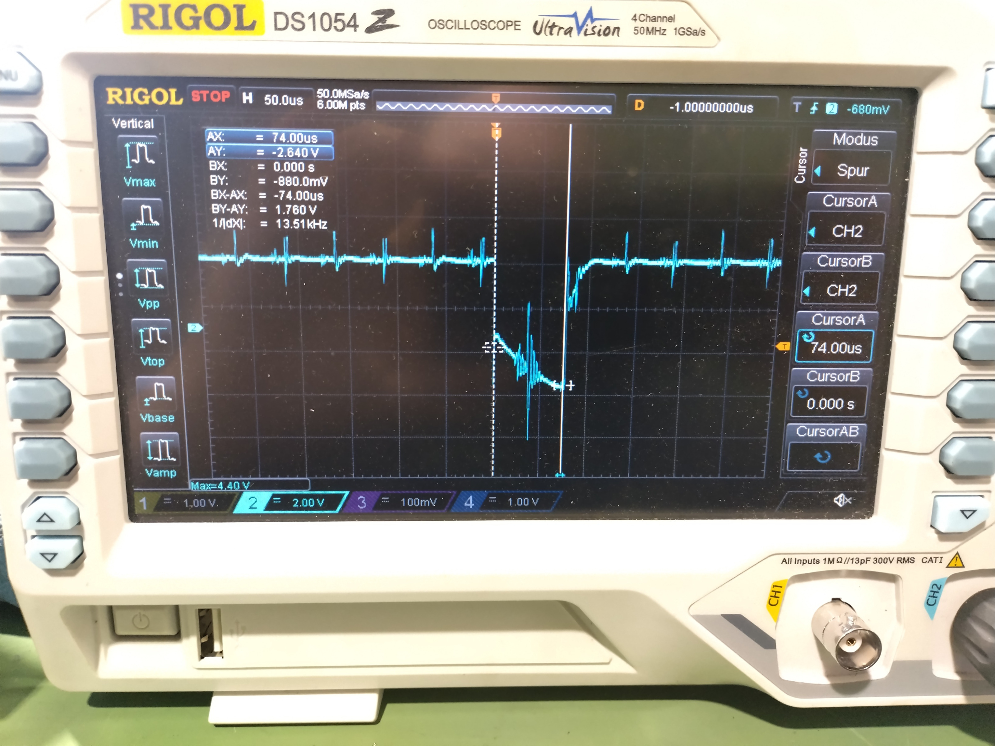
Index signal: Both HALScope and a “real oscilloscope” detect the index signal. It is not as clean as I would like it to be, but the pulse is clearly there, and the Z axis that works fine looks the same.

If anyone has an idea where this could come from, I would be thankful.
The following user(s) said Thank You: RotarySMP

Please Log in or Create an account to join the conversation.

More
6 months 2 weeks ago #345598 by RotarySMP
You are making great progress. Took me a year to get that far :)

I can't say why it is not working as it is, but I have no linear scales, so my homing is just the home Hal switch and then fine tuned off the motor encoder index, and that is rock solid. Could you ignore the linear scale, and home the same as mine (which I think is original Schaublin)?

Please upload some pictures of your linear encoder installations.
Cheers,
Mark

Please Log in or Create an account to join the conversation.

More
6 months 2 weeks ago - 6 months 2 weeks ago #345599 by Dudelbert
I don’t think the linear scales are at fault. I tested them over the 20 mm range of my longest indicator in 1 mm steps, and that is flawless for both axes. I also had the axis move over nearly its full range for 5 minutes at rapid speeds and then come back to the indicator, again, no measurable deviation.

To test the motor encoder directly, I would have to solder them in, and I cannot imagine that this will be better, as I already use the index from there. But if I don’t have any other options, I may as well try it.

I can make some pictures tomorrow, do you mean the mechanical installation on the machine or the wiring, or both?
Last edit: 6 months 2 weeks ago by Dudelbert.
The following user(s) said Thank You: RotarySMP

Please Log in or Create an account to join the conversation.

Time to create page: 0.082 seconds
Powered by Kunena Forum