Considering a Full Rewire on a Working Schaublin 125 CNC

More
6 months 2 weeks ago #345601 by RotarySMP
I don't think you need to wire the motor encoder A and B signals in to LinuxCNC to try it. It is a standard LinuxCNC option to home to switch (Hal switch) and then to the next encoder count, which you already have wired in.

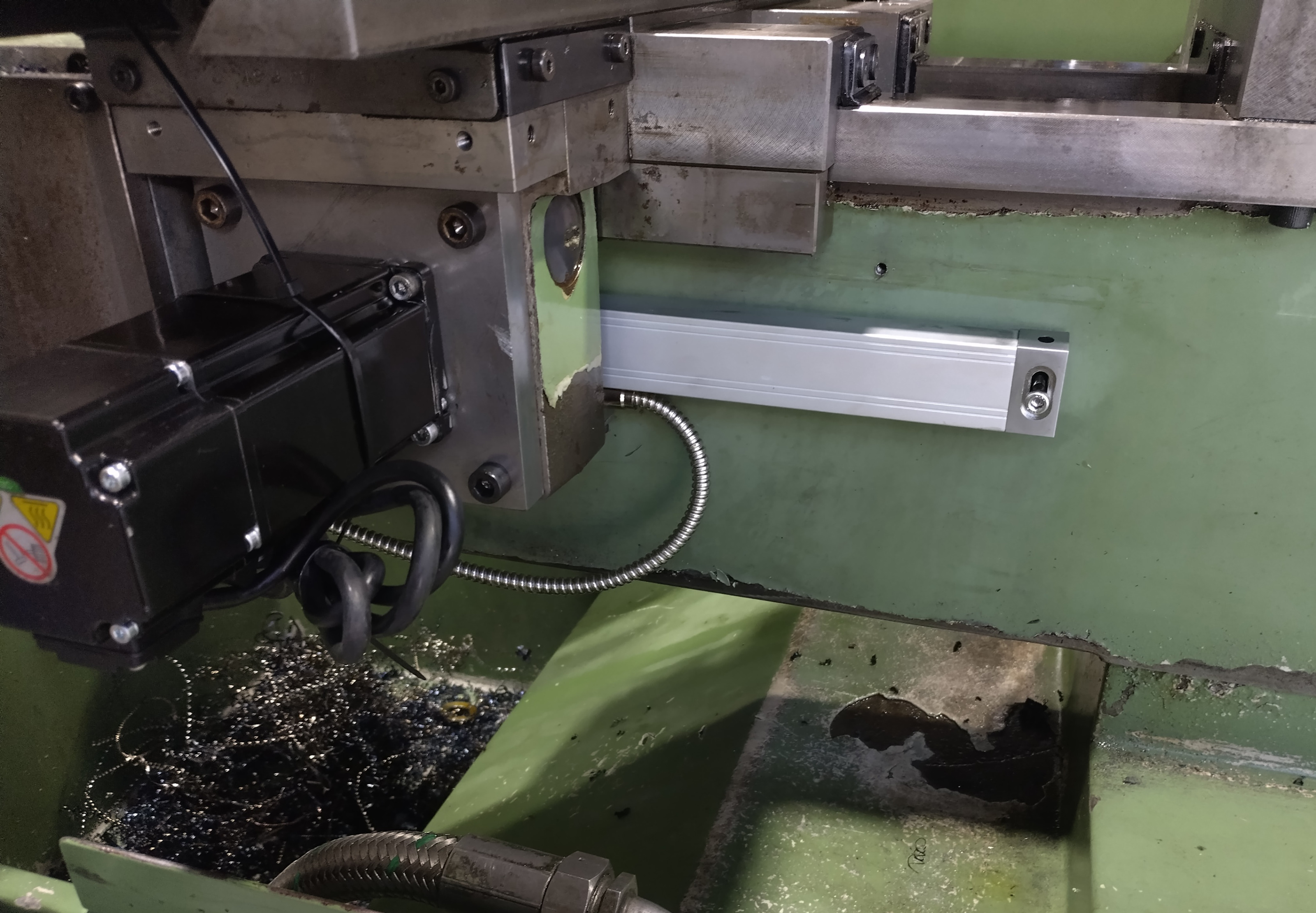
I am interested to see how they did the physical installation of the linear encoders. I considered adding them to mine, but didn't.

Please Log in or Create an account to join the conversation.

More
6 months 2 weeks ago - 6 months 2 weeks ago #345602 by Dudelbert
The previous owner installed a magnetic encoder on the X axis. I did not disassemble it, so all there is to see is a thin cable coming out.

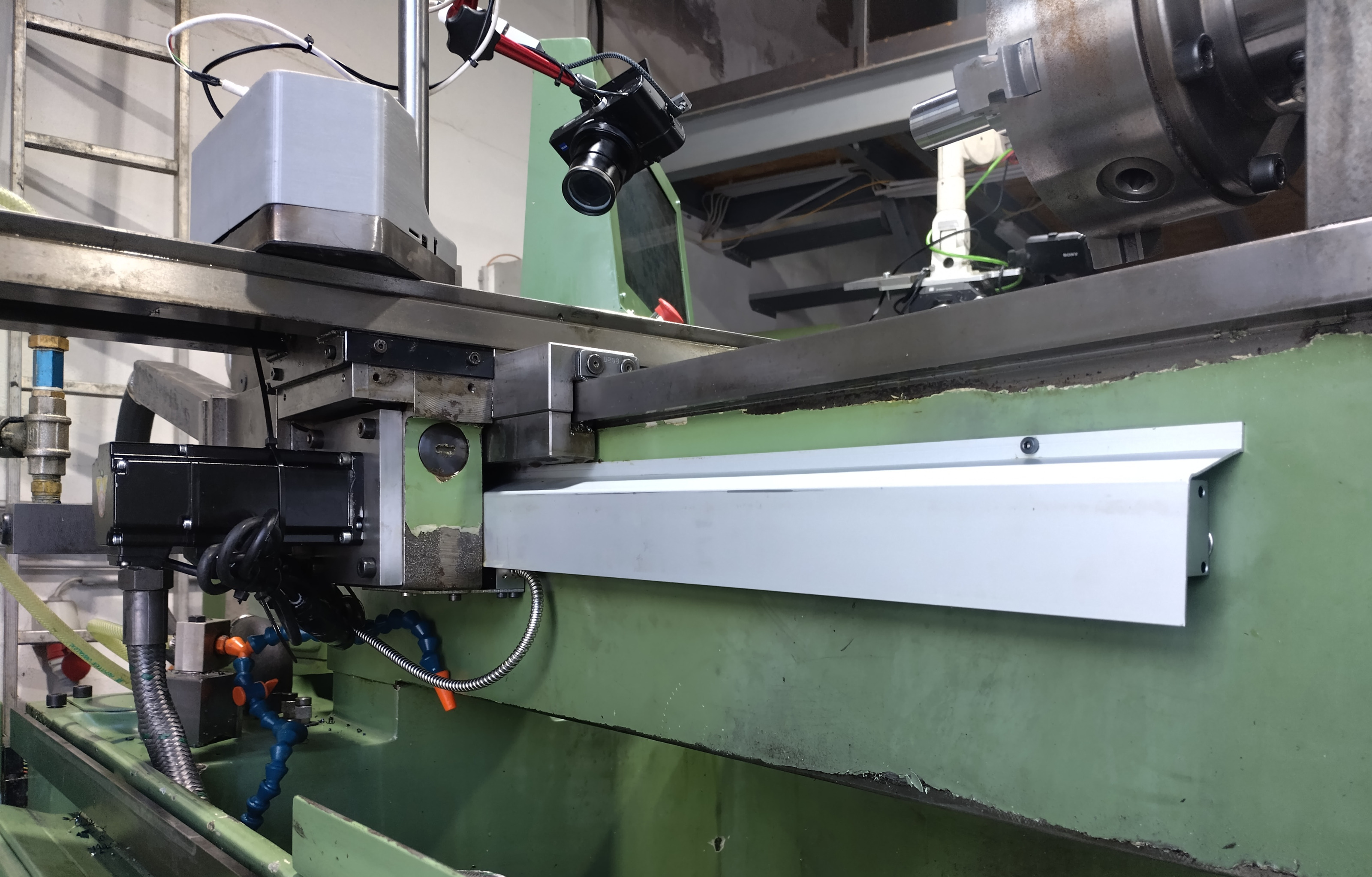
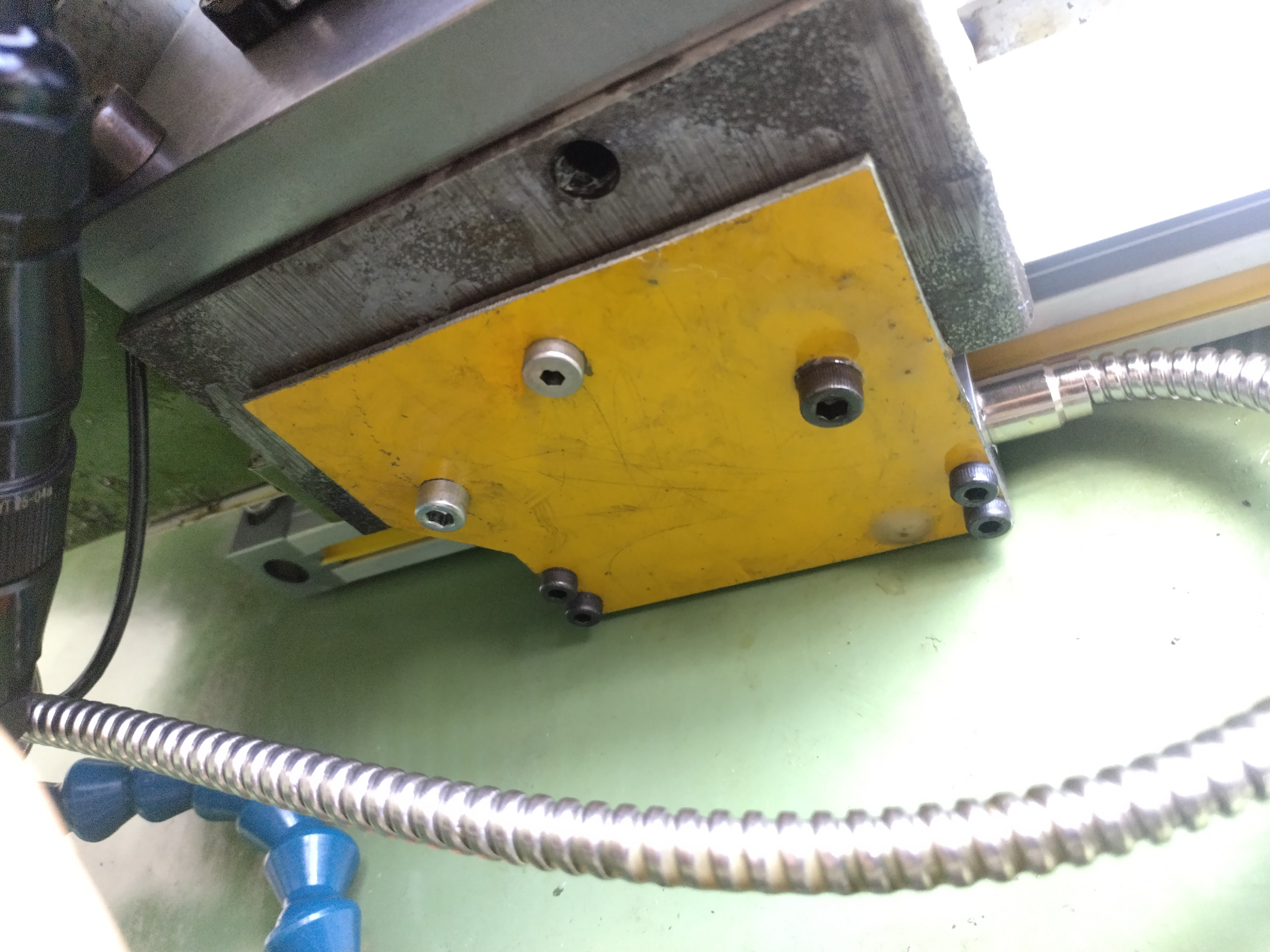
I installed a glass scale on Z. I will make photos tomorrow, there is perfect space for it behind the X-axis motor mount. The installation was really easy.

Oh, and to “home to switch (hall switch) and then to the next encoder count” that is what I did initially. That way I got about 0.4 mm variability on X.
Last edit: 6 months 2 weeks ago by Dudelbert.

Please Log in or Create an account to join the conversation.
More
6 months 2 weeks ago #345605 by RotarySMP
Since there are two Hall sensor triggers on X, do you get the same errors homing off each?
The following user(s) said Thank You: Dudelbert

Please Log in or Create an account to join the conversation.
More
6 months 2 weeks ago #345607 by Dudelbert
Oh, I had forgotten about that. I will try if that works. Thanks for the idea.

Please Log in or Create an account to join the conversation.
More
6 months 2 weeks ago #345648 by Dudelbert
So,

I have a great update. I got the machine working. Using the X-minus hall switch did not do the trick. Testing everything that I already thought was not the problem gave me the solution. The magnetic linear encoder in the X axis was the problem.

I did most of the testing of it at low speeds and short distances, as my indicators obviously cannot measure the length of the full axis. I can remember doing a test running the whole axis at rapid speed for multiple minutes, but I may have done this only on Z, it was two weeks ago. Or it got worse somehow, I don’t know.

In the end, using the motor encoder resolved all the problems.

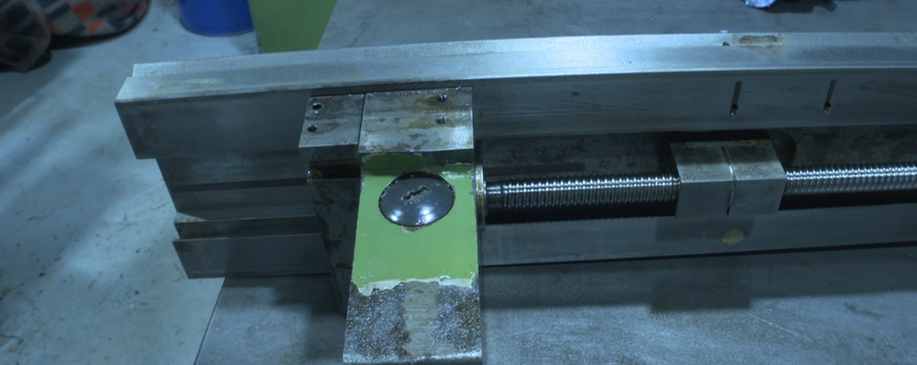
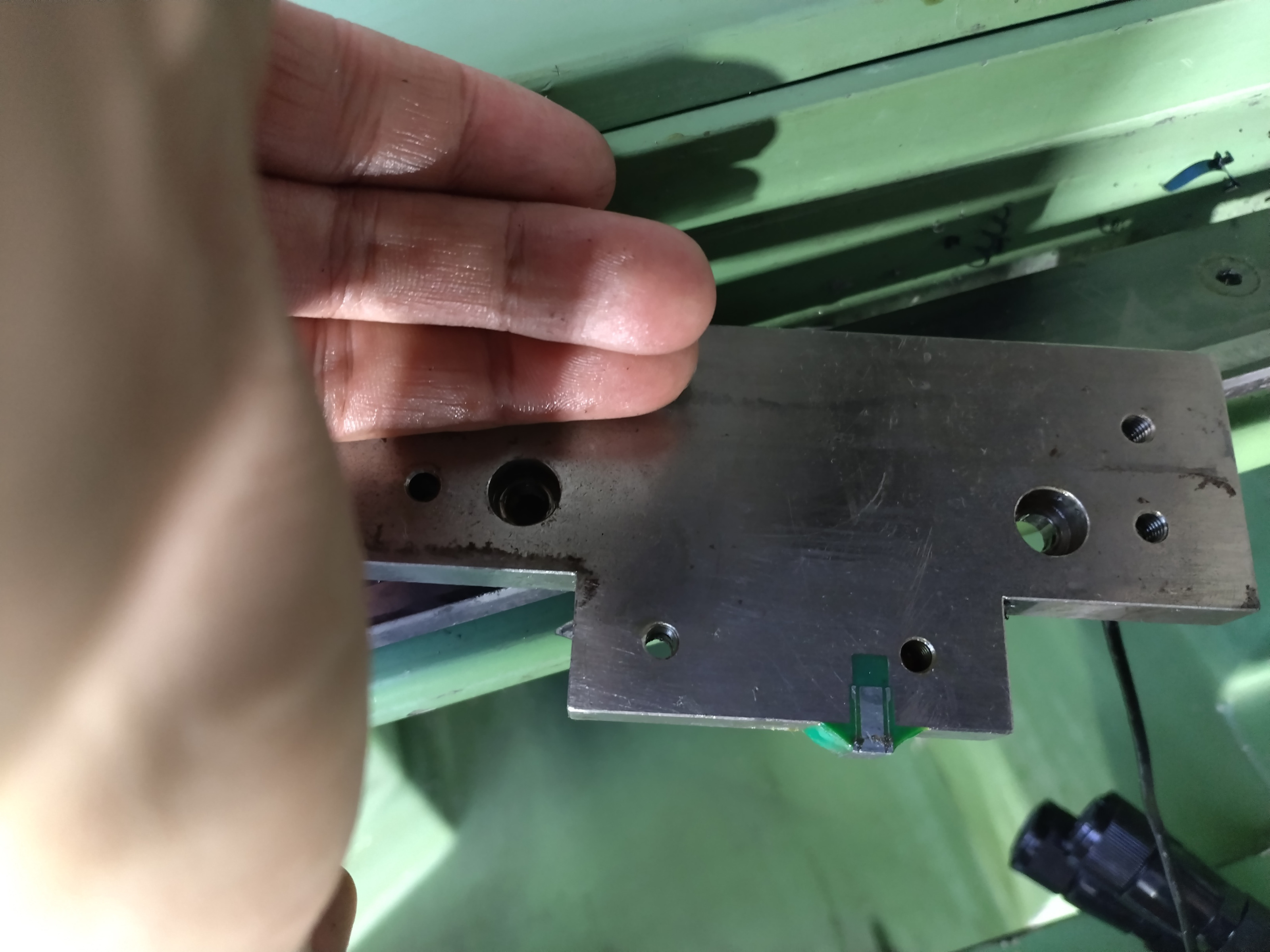
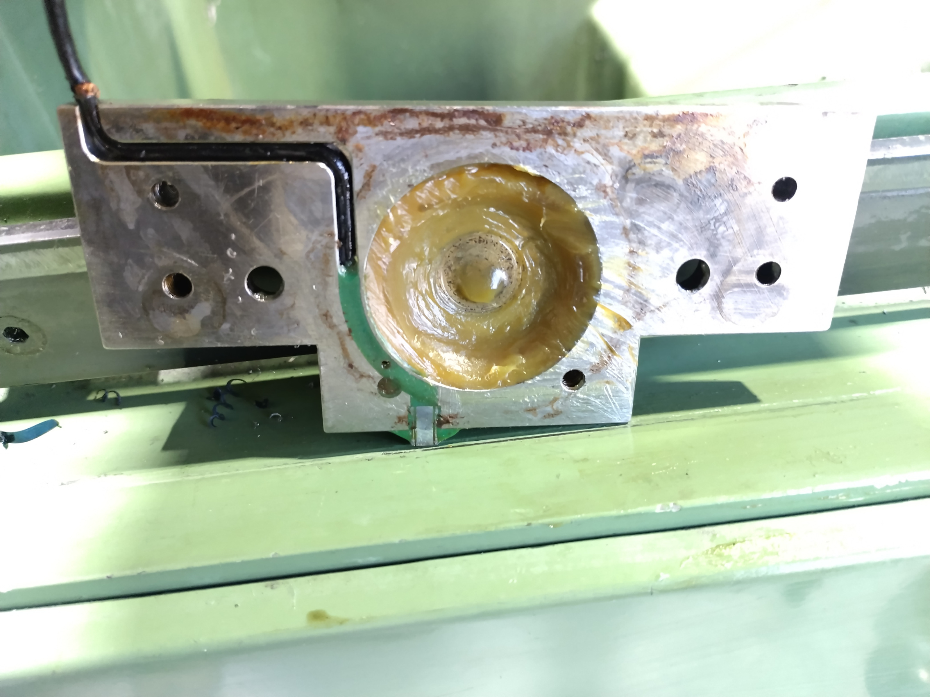
I also disassembled the X axis to see how the encoder is installed. There is a very small read head in the plate behind the thrust bearing for the ballscrew and a putted scale in the underside of the X-axis slide.

I also made some pictures of the Z-axis encoder.

And then, after I spent all day getting this done, I was able to actually make op 1 on the test parts I wanted to make as test parts.
The following user(s) said Thank You: tommylight

Please Log in or Create an account to join the conversation.
More
6 months 2 weeks ago #345656 by andypugh
If I was trying to retrofit the Schaublin I think I would take an approach like this:

1) Use one PID to operate the variator, Use this as the main speed control.
2) Use a second PID to control the VFD, but have this set up to default to 50 (or 60) Hz when disabled. The pid component appears to set the output to zero when disabled, so you might have to use sum2 to add on 50Hz / 3000rpm / whatever to the output.

Then the idea would be to use the variator for speeds inside it's operable range, but then enable the VFD PID to extend that range when the variator is on the end-stops.

Incidentally, the PID gains are full HAL pins. The "lincurve" compoinent was written to allow for dynamic gains to be fed into the PID, if you did need to tune differently for different gears.

Please Log in or Create an account to join the conversation.
Time to create page: 0.299 seconds
Powered by Kunena Forum