Another Biesse Rover 322

More
4 years 8 months ago #233782 by ehb
Replied by ehb on topic Another Biesse Rover 322
So I think I've finished listing all the I/Os of the machine and made a setup table (attached zipped ods-file for LibreOffice Calc). Especially the third table ("Mesa") in the document is of interest, as it lists connections of all Mesa in- and outputs. Red text is either still unclear or gets new wires.

The labels on the solenoid valves were gone so I had to trace cables and re-label them. Could've done without, probably, but I know it would've bitten me in the long run. :-)

Some cat6 patch cables should arrive today, also some mesa card mounting plates a friend of mine milled for me (on a 2012 self-made gantry mill, of course running LinuxCNC). Cable lengths are 2x 15m from cabinet to top of machine, 1x 10 m to the left and 1x 15 m to the right. Might have to shorten the latter two.

Questions to bevins or other Biesse retrofitters:
- On top of the Y-axis, there are two inputs called "Limit switch SX" and "Limit switch DX", in addition to the home switches (which go directly to the cabinet) and the limit switches which go to the drives. What are those two inputs for?
- In an earlier post you mentioned there's a pin on the drive connector which should be grounded to get them enabled. As far as I can tell, the machine has this relay K125 which enables all drives?
- According to the schematic, "axis OK" (or drive-ready or however you want to call it) goes from pin 27 (-) on a drive to a cabinet input module. Did you change this to pin 28 (+) for the sinking inputs of a 7i77?
- It'd be great to get some sample configurations of other Biesses, especially 322, for getting a hang of M6 remap etc. I'm sure Masiwood123 would be really interested too. :-) (according to this post on his Biesse 316 retrofit )

Hopefully I'll have all the stuff ready to mount the new cards, it's getting interesting. :-)

Please Log in or Create an account to join the conversation.
More
4 years 8 months ago #233793 by bevins
Replied by bevins on topic Another Biesse Rover 322
The two switches are probably the two limit switches for that axis and they should be going directly to the drive. Thats kind of weired because your drawings show them labled different.

The Yaskawa drives need a gnd to enable, which is coming from your K125 relay, which actually sends the gnd through it directly to the drive. If you want to interface inputs on the drive with your 7i77 you would probably need a relay. To enable the drives you just need to energioze the K125 relay which that input should have been coming from the controller you removed.

If you want to bring the drive ok into Linuxcnc, then energize a relay and take the inputs into the 7i77. Thats the way I did it.
Not sure what module the drive ok is going to. Can you see it in the schematics?

You can look at my remap stuff but it is in pythonn though. Not sure if that is the best route for you.  You would probably want to do it in NGC remap.

Just my 2 cents


The following user(s) said Thank You: ehb

Please Log in or Create an account to join the conversation.
More
4 years 8 months ago #233800 by ehb
Replied by ehb on topic Another Biesse Rover 322
Hey Bob, great to hear from you!

I might have found out what those limit switches are! They're extra limit switches when using the left and right areas of the machine separately. Milling on one side, placing parts on the other side. So that's something I'm not going to need. :-) They were going to module1 on top of the machine.

Alright, so K125 can stay and should activate all axis by grounding. That's good and easy.

All "Axis OK" originally go to module 7 in the cabinet which is a SIR88. I was under the impression all these modules had sinking inputs, but the ones in the cabinet might be different. I'll look into this a bit more. As you said, a guy can always put a relay in between. Thanks!

And sure I'd like to see your python stuff. If I decide to go the proper route, I'll still be able to deduct some logic from your code, hopefully. :-)

Thanks as always!

Please Log in or Create an account to join the conversation.

More
4 years 8 months ago #233802 by bevins
Replied by bevins on topic Another Biesse Rover 322

Hey Bob, great to hear from you!

I might have found out what those limit switches are! They're extra limit switches when using the left and right areas of the machine separately. Milling on one side, placing parts on the other side. So that's something I'm not going to need. :-) They were going to module1 on top of the machine.

Alright, so K125 can stay and should activate all axis by grounding. That's good and easy.

All "Axis OK" originally go to module 7 in the cabinet which is a SIR88. I was under the impression all these modules had sinking inputs, but the ones in the cabinet might be different. I'll look into this a bit more. As you said, a guy can always put a relay in between. Thanks!

And sure I'd like to see your python stuff. If I decide to go the proper route, I'll still be able to deduct some logic from your code, hopefully. :-)

Thanks as always!


SIR88 is the rs485 relay inut modules?

I am prtetty sure they use 24v for their field power and if you use the 3 phase rectifier for your field voltage, you can use the inputs straight off the module, but you would need to check. I will look at the schematics. But Biesse usually does it that way.

So just energize the K125 relay to enable the drives.

My code is on github.     Rover 346 remap and config
 
The following user(s) said Thank You: ehb

Please Log in or Create an account to join the conversation.

More
4 years 8 months ago #233828 by ehb
Replied by ehb on topic Another Biesse Rover 322
Thanks a lot for the link to your github repo! That's a lot of code, but I see comments and readable function and variable names. I like that so far! :-)

Regarding modules: As I said, CNi did not have any documentation about the communication protocol, but they sent me two-page brochures of SI816N, SIR88N, SI24N, SO24N and SO816. I've attached the PDF for SIR88N. My modules only say SIR88, without the N, so I'm not sure if they just omitted the N on the front lable or if they're two different things.
If my Biesse indeed has the SIR88N, then according to the PDF, the inputs should be sinking, which contradicts what the Biesse schematics and Yaskawa manual say.

About field voltages: Some of the Mesa cards have VIN and VFIELD separate. I was thinking about putting P1 on VIN and P2/P3 (depending on the module position) to VFIELD. Did you do the same?

Please Log in or Create an account to join the conversation.

More
4 years 8 months ago - 4 years 8 months ago #233831 by ehb
Replied by ehb on topic Another Biesse Rover 322
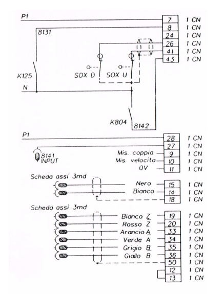
This is page 72 from the Biesse schematics. On the left side, we see input 8141 going to pin 27 on the Yaskawa drive connector (X) in this case).
 

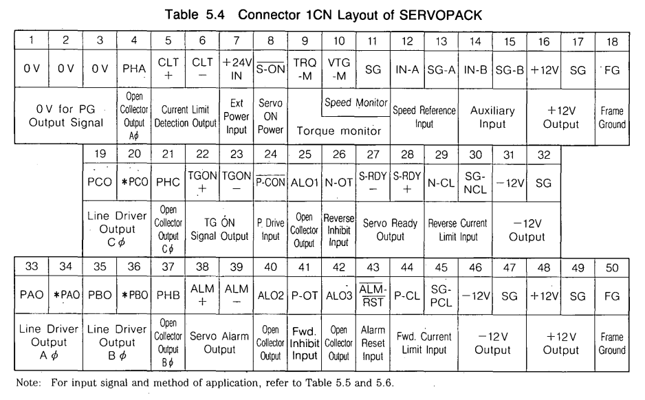
And this the connector pinout from the Yaskawa manual.
 

In fact, I now see P1 is connected to pin 28 - so I guess it's an isolated output which sources whatever is connected on pin 28 to pin 27. Which would indeed make the inputs sinking, which also means I was on the wrong track for a whole while and I can just hook this cable (pin 27, formerly going to input 8141) up to a 7i77 input.
I think I see clearly now, or am I wrong again?
Last edit: 4 years 8 months ago by ehb.

Please Log in or Create an account to join the conversation.

Time to create page: 0.089 seconds
Powered by Kunena Forum
