
- Posts: 2180
- Thank you received: 905
1 or 2 dedicated 120VAC circuits for my CNC?
- spumco
- Offline
- Platinum Member
-

Less
More
3 years 7 months ago #267450
by spumco
Replied by spumco on topic 1 or 2 dedicated 120VAC circuits for my CNC?
No eBay APP ID and/or Cert ID defined in Kunena configuration
Each output is shared with 7 others on a single driver chip. Each driver chip can handle 1.4a total. So you can have one output sinking 1.39A, but if another output turns on the chip will go in to thermal shutown. If you're using all 8 at the same time you get 1.4/8a (0.175a).
Tommy's right (as usual) - you need another relay between the contactor and the Mesa output. The additional relay should have a built-in flyback diode just to be safe.
When I had to re-do some of my stuff - mentioned earlier - I switched from the mechanical relays I'd been using to solid-state transitor relays. Not the big boxy SSR's for high-amp use, but small DIN-rail optocouplers used for low-amp switching.
Here's a Murr Elektronic optocoupler rated for 10A and operates at 24vdc:
[url][/url]
But if you've already got a small 5A relay that'll fit in the cabinet you can add a diode to the coil and switch the contactor with that.
Having a hard time determining what exactly I am comparing.
MAXIMUM PER CHIP CURRENT
Because of thermal limitations there is a maximum per driver chip total current of 1.4 amps continuous. Each driver chip connects to 8 sequential outputs. If this limit is exceeded, the driver chip may go into thermal shutdown.
Each output is shared with 7 others on a single driver chip. Each driver chip can handle 1.4a total. So you can have one output sinking 1.39A, but if another output turns on the chip will go in to thermal shutown. If you're using all 8 at the same time you get 1.4/8a (0.175a).
Tommy's right (as usual) - you need another relay between the contactor and the Mesa output. The additional relay should have a built-in flyback diode just to be safe.
When I had to re-do some of my stuff - mentioned earlier - I switched from the mechanical relays I'd been using to solid-state transitor relays. Not the big boxy SSR's for high-amp use, but small DIN-rail optocouplers used for low-amp switching.
Here's a Murr Elektronic optocoupler rated for 10A and operates at 24vdc:
[url][/url]
But if you've already got a small 5A relay that'll fit in the cabinet you can add a diode to the coil and switch the contactor with that.
The following user(s) said Thank You: tommylight, Sray69
Please Log in or Create an account to join the conversation.
- Sray69
- Offline
- Elite Member
-

Less
More
- Posts: 255
- Thank you received: 13
3 years 7 months ago #267452
by Sray69
Replied by Sray69 on topic 1 or 2 dedicated 120VAC circuits for my CNC?
Thanks for the info. I will give this a shot.
I may have an extra Omron 10amp relay left over. Will have to look through my stuff. If not I will try a SSR.
I may have an extra Omron 10amp relay left over. Will have to look through my stuff. If not I will try a SSR.
Please Log in or Create an account to join the conversation.
- Sray69
- Offline
- Elite Member
-
Less
More
- Posts: 255
- Thank you received: 13
3 years 7 months ago - 3 years 7 months ago #267622
by Sray69
Replied by Sray69 on topic 1 or 2 dedicated 120VAC circuits for my CNC?
I didn't have the Omron relay but I did have a SSR (10A) that I ended up replacing with the Omron's. I figured I would test this and see if it would work.
Unfortunately I cannot get it to work. Maybe I am hooking it up incorrectly. I am not sure. The way I had the circuit setup originally was that I had the 24V signal coming from the output pin 01 (Mesa) to the A1 terminal and the A2 terminal (on the contactor) going to DC ground in the cabinet.
All I did was install the SSR inline with neg-neg and pos-pos with a diode on the input side (with stripe toward the positive side). See image.
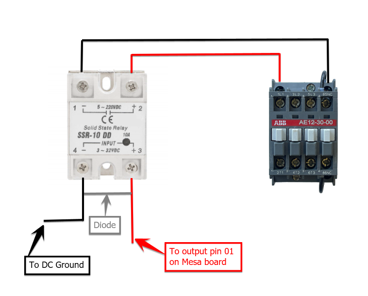
Is this the correct way to connect it?
NOTE: I do not show the high voltage connections on the contactor.
When I enable the circuit I get a red light on the SSR. When I test the voltage I am getting 24V on the input side and zero volts on the output side.
Unfortunately I cannot get it to work. Maybe I am hooking it up incorrectly. I am not sure. The way I had the circuit setup originally was that I had the 24V signal coming from the output pin 01 (Mesa) to the A1 terminal and the A2 terminal (on the contactor) going to DC ground in the cabinet.
All I did was install the SSR inline with neg-neg and pos-pos with a diode on the input side (with stripe toward the positive side). See image.
Is this the correct way to connect it?
NOTE: I do not show the high voltage connections on the contactor.
When I enable the circuit I get a red light on the SSR. When I test the voltage I am getting 24V on the input side and zero volts on the output side.
Last edit: 3 years 7 months ago by Sray69.
Please Log in or Create an account to join the conversation.
- spumco
- Offline
- Platinum Member
-
Less
More
- Posts: 2180
- Thank you received: 905
3 years 7 months ago #267623
by spumco
Replied by spumco on topic 1 or 2 dedicated 120VAC circuits for my CNC?
1. Is your SSR rated for DC switching? Most of the box/puck types I've seen are for AC only. If your picture is of your actual SSR, you're fine.
2. What is powering the load side of the SSR? remember - it's a switch. It does't pass voltage through from the control side to the load side.
The load side (contactor side) needs a power supply. Assuming your contactor coil is 24vdc, your circuit should be:
+24vdc -> SSR+(2) (power supply V+ to SSR+)
SSR-(1) -> contactor A1 (SSR- to contactor coil V+)
contactor A2 -> 0VDC (contactor coil to power supply V-)
3. Assuming you're powering the contactor coil from the same PSU as that which is powering the Mesa... put the diode across the contactor coil and not the SSR. The SSR turning off doesn't create a reverse voltage spike, but the contactor coil will - and that may work it's way back to the Mesa without a flyback diode. Connect the diode acrosss contactor A1 & A2, with the stripe to the A1 side.
The following user(s) said Thank You: Sray69
Please Log in or Create an account to join the conversation.
- Sray69
- Offline
- Elite Member
-
Less
More
- Posts: 255
- Thank you received: 13
3 years 7 months ago #267624
by Sray69
Replied by Sray69 on topic 1 or 2 dedicated 120VAC circuits for my CNC?
YES! Thanks. I had a feeling I needed to run power through the output terminals on the SSR instead of how I had it hooked up. I just was not sure where the power should come from.
So just to be clear, I should run the power for the contactor from the 24VDC PSU directly and not from field power/ground on the Mesa?
So just to be clear, I should run the power for the contactor from the 24VDC PSU directly and not from field power/ground on the Mesa?
Please Log in or Create an account to join the conversation.
- Sray69
- Offline
- Elite Member
-
Less
More
- Posts: 255
- Thank you received: 13
3 years 7 months ago #267632
by Sray69
Replied by Sray69 on topic 1 or 2 dedicated 120VAC circuits for my CNC?
Nevermind! I got it! Thanks for the guidance. My brain is mush.
Not sure why the red light on the SSR when it is enabled. I normally expect green for go and red for no-go. LOL. But whatever. It works.
Not sure why the red light on the SSR when it is enabled. I normally expect green for go and red for no-go. LOL. But whatever. It works.
Please Log in or Create an account to join the conversation.
Time to create page: 0.143 seconds