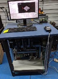
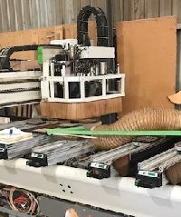
Biesse Rover 346 Retrofit
- bevins
-
 Topic Author
- Offline
- Platinum Member
-

Less
More
- Posts: 1942
- Thank you received: 338
12 Sep 2017 12:43 #98880
by bevins
Replied by bevins on topic Biesse Rover 346 Retrofit
I cant think of a reason to change tools in both spindles other than saving 15 seconds if you are on one end of the table to go back and change tools.
Just my thoughts.
Just my thoughts.
Please Log in or Create an account to join the conversation.
- bevins
-
 Topic Author
- Offline
- Platinum Member
-

Less
More
- Posts: 1942
- Thank you received: 338
12 Sep 2017 12:45 #98882
by bevins
I have the same VFD. You don't need to communicate with it. It has a pot connection. You just connect the 7i77 spindle out to those connections, then use the rpm output to go into 7i77 analog input so Linuxcnc knows the spindle speed and its done. Works like a charm.
Replied by bevins on topic Biesse Rover 346 Retrofit
My machine has 2 spindles, 10 place toolchanger, one 4th axis that can be fit with a circular saw, and an additional horizontal spindle intended for manufacturing doors ("Schlosskasten"), all on one VFD.
The machine is running more or less, but I haven't figured out/implemented tool-change yet, and communication with the VFD (a control techniques model) doesn't exist yet.
I have the same VFD. You don't need to communicate with it. It has a pot connection. You just connect the 7i77 spindle out to those connections, then use the rpm output to go into 7i77 analog input so Linuxcnc knows the spindle speed and its done. Works like a charm.
Please Log in or Create an account to join the conversation.
- Todd Zuercher
-

- Offline
- Platinum Member
-

Less
More
- Posts: 4689
- Thank you received: 1433
12 Sep 2017 13:42 #98889
by Todd Zuercher
I don't think he is referring to committing specific tool pockets on the tool changer to any one spindle. He is talking about committing sections of the tool table in Linuxcnc (I think the tool table has a size limit of 56 positions). Lets say you have a 15 tool position changer that can be accessed by 3 spindles. The tool table would need to have 3 sections of 15 tools, so in the table you would have tools 1-15 be for spindle #1, 21-35 be for spindle #2, and 41-55 be for spindle #3. In the table tool number 1,21,41 would all refer to the same tool and tool pocket in the tool changer, just in a different spindle, same for 5, 25, 45...
Replied by Todd Zuercher on topic Biesse Rover 346 Retrofit
I don't really like committing half the tool pockets to one spindle, but it certainly seems possible, and should be better than nothing. Should be a useful next step after getting the tool changer to work with one spindle. Thanks.
I don't think he is referring to committing specific tool pockets on the tool changer to any one spindle. He is talking about committing sections of the tool table in Linuxcnc (I think the tool table has a size limit of 56 positions). Lets say you have a 15 tool position changer that can be accessed by 3 spindles. The tool table would need to have 3 sections of 15 tools, so in the table you would have tools 1-15 be for spindle #1, 21-35 be for spindle #2, and 41-55 be for spindle #3. In the table tool number 1,21,41 would all refer to the same tool and tool pocket in the tool changer, just in a different spindle, same for 5, 25, 45...
Please Log in or Create an account to join the conversation.
- bevins
-
 Topic Author
- Offline
- Platinum Member
-

Less
More
- Posts: 1942
- Thank you received: 338
12 Sep 2017 14:07 #98892
by bevins
Yes but the remap will be really complicated. And then the second spindle cant even access the full 4X11. So I didnt see the need for the second spindle for the toolchange.
Replied by bevins on topic Biesse Rover 346 Retrofit
I don't really like committing half the tool pockets to one spindle, but it certainly seems possible, and should be better than nothing. Should be a useful next step after getting the tool changer to work with one spindle. Thanks.
I don't think he is referring to committing specific tool pockets on the tool changer to any one spindle. He is talking about committing sections of the tool table in Linuxcnc (I think the tool table has a size limit of 56 positions). Lets say you have a 15 tool position changer that can be accessed by 3 spindles. The tool table would need to have 3 sections of 15 tools, so in the table you would have tools 1-15 be for spindle #1, 21-35 be for spindle #2, and 41-55 be for spindle #3. In the table tool number 1,21,41 would all refer to the same tool and tool pocket in the tool changer, just in a different spindle, same for 5, 25, 45...
Yes but the remap will be really complicated. And then the second spindle cant even access the full 4X11. So I didnt see the need for the second spindle for the toolchange.
Please Log in or Create an account to join the conversation.
- rmu
-

- Offline
- Elite Member
-

Less
More
- Posts: 279
- Thank you received: 100
13 Sep 2017 17:12 #98925
by rmu
Replied by rmu on topic Biesse Rover 342 circuit diagram
I just managed to upload the circuit diagram for my Biesse Rover 342. Reconstructed more or less from original documentation plus measurements and tracing wires, as circuit diagrams were not complete. Maybe some details are still missing. I used
qelectrotech
, PDF rendering is included. Most things are in german, but it should be easy to translate. Maybe somebody finds this useful.
bitbucket.org/rmu/biesse-rover-circuit-diagram
bitbucket.org/rmu/biesse-rover-circuit-diagram
Please Log in or Create an account to join the conversation.
- Pa
- Offline
- New Member
-

Less
More
- Posts: 1
- Thank you received: 0
10 May 2020 08:30 #167240
by Pa
Replied by Pa on topic Biesse Rover 346 Retrofit
Hello,
I also bought a Biesse. I have a couple of questions about the Yaskawa CACR-SRxxBE 1 2G-E drivers. Maybe Bevins or 9thraven or other forum members, who are faced with CACR SR can help me?
I will use 5i25 and 7i77.
The first question about encoder signals from CACR drivers. I can't find the output voltage of these signals (A, /A, B /B, Z, /Z). The 7i77 accepts 5v encoder signals, so I need to know what signal voltage is coming.
Second question about analog signal to driver. 7i77 will generate +-10V, but in different places I find different information about the control voltage received by the driver. Attach what the instruction writes. My question is whether these drivers are really controlled by + -10V ?
Regards
Please Log in or Create an account to join the conversation.
- bevins
-
 Topic Author
- Offline
- Platinum Member
-

Less
More
- Posts: 1942
- Thank you received: 338
10 May 2020 14:19 - 10 May 2020 14:20 #167266
by bevins
These drives are definately +-10v. 7i77 works well with them.
The encoders are 5v and work great with the 7i77. Dont overthink it. Just connect them and on to the next issue.
What will take most of your time is figuring out their prestart ritual with their green lite button.
and interfacing that with estop circuit. Let me know if you need help with it.
Replied by bevins on topic Biesse Rover 346 Retrofit
Hello,
I also bought a Biesse. I have a couple of questions about the Yaskawa CACR-SRxxBE 1 2G-E drivers. Maybe Bevins or 9thraven or other forum members, who are faced with CACR SR can help me?
I will use 5i25 and 7i77.
The first question about encoder signals from CACR drivers. I can't find the output voltage of these signals (A, /A, B /B, Z, /Z). The 7i77 accepts 5v encoder signals, so I need to know what signal voltage is coming.
Second question about analog signal to driver. 7i77 will generate +-10V, but in different places I find different information about the control voltage received by the driver. Attach what the instruction writes. My question is whether these drivers are really controlled by + -10V ?
Regards
These drives are definately +-10v. 7i77 works well with them.
The encoders are 5v and work great with the 7i77. Dont overthink it. Just connect them and on to the next issue.
What will take most of your time is figuring out their prestart ritual with their green lite button.
and interfacing that with estop circuit. Let me know if you need help with it.
Last edit: 10 May 2020 14:20 by bevins.
Please Log in or Create an account to join the conversation.
- FaniePotgieter
- Offline
- New Member
-

Less
More
- Posts: 1
- Thank you received: 0
18 Aug 2020 14:38 #178603
by FaniePotgieter
Replied by FaniePotgieter on topic Biesse Rover 346 Retrofit
Hello. I'm new to this forum, but i joined specifically to see how other guys / girls have gone about retrofitting older cnc routers to linux etc.
I have a Masterwood Project 313 with a CN6 controller, but is has limited capabilities, and I would like to use it in more of a carving role.
How have you gone about doing it, and where do I start.
Any advice will be appreciated
I have a Masterwood Project 313 with a CN6 controller, but is has limited capabilities, and I would like to use it in more of a carving role.
How have you gone about doing it, and where do I start.
Any advice will be appreciated
Please Log in or Create an account to join the conversation.
- Todd Zuercher
-

- Offline
- Platinum Member
-

Less
More
- Posts: 4689
- Thank you received: 1433
18 Aug 2020 14:55 - 18 Aug 2020 14:59 #178607
by Todd Zuercher
Replied by Todd Zuercher on topic Biesse Rover 346 Retrofit
Probably should start a new thread for your question(s).
But the first step is to figure out how the axis motors on your router are controlled (what kind of command signal). Are they step-motors or servos that accept step/dir commands, or is the servo loop closed in the control using analog commands, or something different? Also your spindle VFD(s) and how they can be controlled.
The next step is to determine how many digital IO points you will need and what electrical properties they have (limit switches, pressure switches, relays...)
Once you've gathered all of that information, you are ready to decide what interface hardware you will need/want to buy.
Last edit: 18 Aug 2020 14:59 by Todd Zuercher. Reason: reworded a sentence for clarity.
Please Log in or Create an account to join the conversation.
- SPH
-

- Offline
- Premium Member
-

Less
More
- Posts: 109
- Thank you received: 6
08 Jan 2021 05:18 #194468
by SPH
Replied by SPH on topic Biesse Rover 346 Retrofit
Gday Bevins, do you have the parameter settings somewhere for the Chinese servos you used on that roller rack machine you setup? You mentioned the need to adjust quite a few settings in my rover 23 retrofit thread.
Sorry to drop this here, wasn't sure how else to contact you.
Cheers
Sam
Sorry to drop this here, wasn't sure how else to contact you.
Cheers
Sam
Please Log in or Create an account to join the conversation.
Time to create page: 0.096 seconds
