Mitsubishi RV-6SDL Robot arm Servo/Encoder usability
- Ehsan_R
- Offline
- Premium Member
-

- Posts: 88
- Thank you received: 1
When I saw the robot for the first time, I had the same feeling as youDAMN that looks like something from "Star Wars" movie !
")
Probably very old Kuka robot, so
Do you have the control box for it?
Does it have 320 written on the box or hand controller?
What motors does it use?
Does it have encoders or resolvers on the back of the motors?
When did it have the gearbox oil changed?
Does it have a spring or hydraulic counterbalance?
Edit:
Start a new topic for it, if you already did not.
Thank you.
I also did some searching to understand the model of the robot and find the DH parameters, but I was not successful, and I think that obtaining the DH parameters of this robot is a challenging task.
As for the controller, luckily there's nothing but a couple of brushless servo motors that I don't think I'll be able to use.
I plan to buy some new servo motors for it
In the case of the controller, I was going to use an EtherCAT servo motor, which I will temporarily use some existing servo motors to reduce the cost.
I have some servo motors with incremental encoders that I will be using.
Also, I have designed a header board using litexcnc to connect to servo motors.
Harmonic gearbox is used in the arms, which I think does not need lubrication.
At the back of the robot is an air jack that supports some of the torque applied to the second link.
Please Log in or Create an account to join the conversation.
- Ehsan_R
- Offline
- Premium Member
-
- Posts: 88
- Thank you received: 1
I implemented the configuration you created for the RV-6SDL robot and worked with it in the simulated environment and the result was almost satisfactory. I think I can do what I want with the configuration you have created.
Then I edited the HAL file based on the hardware I had (litexcnc).
There were problems which I will describe to you later.
I have two solutions to generate the gcode file, the first one is to use Axis Position Logger.
In this way, I move the end part of the robot to the desired places and save the position and then move between the saved points.
The problem with this solution is that I don't know how to do circular movements in 3D space.
The second solution is to create complex paths using gcode generation software and place these paths relatively in the final gcode file, which, of course, requires simulating the robot body in software such as robodk.
Please watch the video I linked.
Do you have information about determining the orientation of the end effector of the robot?
And also if you have any tips or suggestions let me know
Please Log in or Create an account to join the conversation.
- Aciera
-
 Topic Author
- Offline
- Administrator
-

- Posts: 4766
- Thank you received: 2138
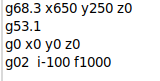
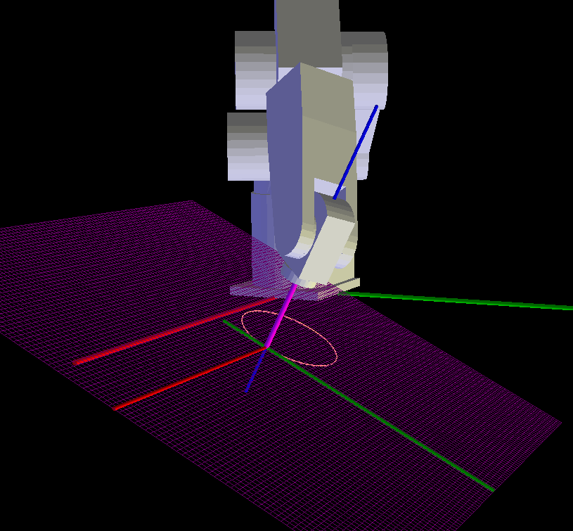
I have done some work in implementing a tilted work plane (TWP) feature for tool-rotation kinematics (which works quite well) and have been working on doing the same for my melfa 6axis robot. I had to abandon 'genserkins' out of lack of understanding and create my own kinematic with twp parameters built in. I have not ironed out all the bugs but the TWP feature looks promising. The path below is the result of just four lines of gcode:
The next hurdle for welding would be to modify the kinematics so the C axis (ie wrist rotation) is done in joint mode (to be able to keep the torch pointing to the center of the arc) instead of doing it in world mode like the position.
So basically you would define the tilted work plane by teaching in the 3 points as in the video (which I have already implemented in my 5axis TWP work) and calculate the center of the arc from the same 3 points.
Mind you all of this would only give you circular (and helical) arc moves which would not let you weld, for example, a pipe joining another pipe.
Attachments:
Please Log in or Create an account to join the conversation.
- Aciera
-
Topic Author
- Offline
- Administrator
-
- Posts: 4766
- Thank you received: 2138
Attachments:
Please Log in or Create an account to join the conversation.
- Aciera
-
Topic Author
- Offline
- Administrator
-
- Posts: 4766
- Thank you received: 2138
Please Log in or Create an account to join the conversation.
- andypugh
-

- Offline
- Moderator
-

- Posts: 19886
- Thank you received: 4645
There was some work done a long time ago on "arbitrary arcs" but it was apparently abandoned.I have done some work in implementing a tilted work plane (TWP) feature for tool-rotation kinematics
github.com/LinuxCNC/linuxcnc/tree/arbitrary-arc (looks like it was 12 years ago)
It does feel like it should be possible to give XYZ and points and IJK centre points to define an arc. It probably needs to be a short arc (less than 180 degrees) as the whole concept of clockwise and anticlockwise loses meaning if the plane is not defined, and if it is exactly 180 degrees there are infinite solutions.
Please Log in or Create an account to join the conversation.
- Aciera
-
Topic Author
- Offline
- Administrator
-
- Posts: 4766
- Thank you received: 2138
It probably needs to be a short arc (less than 180 degrees) as the whole concept of clockwise and anticlockwise loses meaning if the plane is not defined, and if it is exactly 180 degrees there are infinite solutions.
Yes, in the end we still need the plane and normal to define the arc.
[edit] actually looking at the code in the commit the idea was to give the end coordinates the center and the normal so everything is defined.
Please Log in or Create an account to join the conversation.
- tommylight
-

- Offline
- Moderator
-
- Posts: 21764
- Thank you received: 7438
How are we to know it was nonsense?Nonsense deleted
Please Log in or Create an account to join the conversation.
- Aciera
-
Topic Author
- Offline
- Administrator
-
- Posts: 4766
- Thank you received: 2138
")
Please Log in or Create an account to join the conversation.
- andypugh
-
- Offline
- Moderator
-
- Posts: 19886
- Thank you received: 4645
You only need the normal if you want to retain the concept of CW and CCW. If you say that all arcs need to be less than 180 degrees then the start, end and centre define the plane unambiguously, and the defintion that it always chooses the shortest arc defines the direction.
[edit] actually looking at the code in the commit the idea was to give the end coordinates the center and the normal so everything is defined.
That does mean that full turn and multi-turn arcs are not supported.
Do you know if any other control has a paradigm for this? Other than defining ad-hoc planes for each arc, which seems clumsy.
Please Log in or Create an account to join the conversation.